Recessed luminaire adjustment mechanism

a technology of adjustment mechanism and recessed luminaire, which is applied in the direction of lighting device details, lighting support devices, lighting and heating apparatus, etc., can solve the problems of inconvenient and tedious operation, inconvenient installation and tedious operation, etc., and achieve convenient tilting, convenient aiming of light beams, and easy locking of light sources

Active Publication Date: 2015-08-27
ABL IP HLDG
View PDF21 Cites 66 Cited by
  • Summary
  • Abstract
  • Description
  • Claims
  • Application Information

AI Technical Summary

Benefits of technology

[0013]In this manner, the directional recessed luminaire provides for convenient aiming of the light beam from the light source and for easily locking the light source into a desired aiming position. The directional recessed luminaire provides for convenient tilt and rotational adjustment of the light beam from the light source.

Problems solved by technology

For many currently available directional recessed luminaires, this has been an inconvenient and tedious operation.
This makes the installation an inconvenient and tedious operation.

Method used


Image

  • Recessed luminaire adjustment mechanism
  • Recessed luminaire adjustment mechanism
  • Recessed luminaire adjustment mechanism

Examples


Embodiment Construction

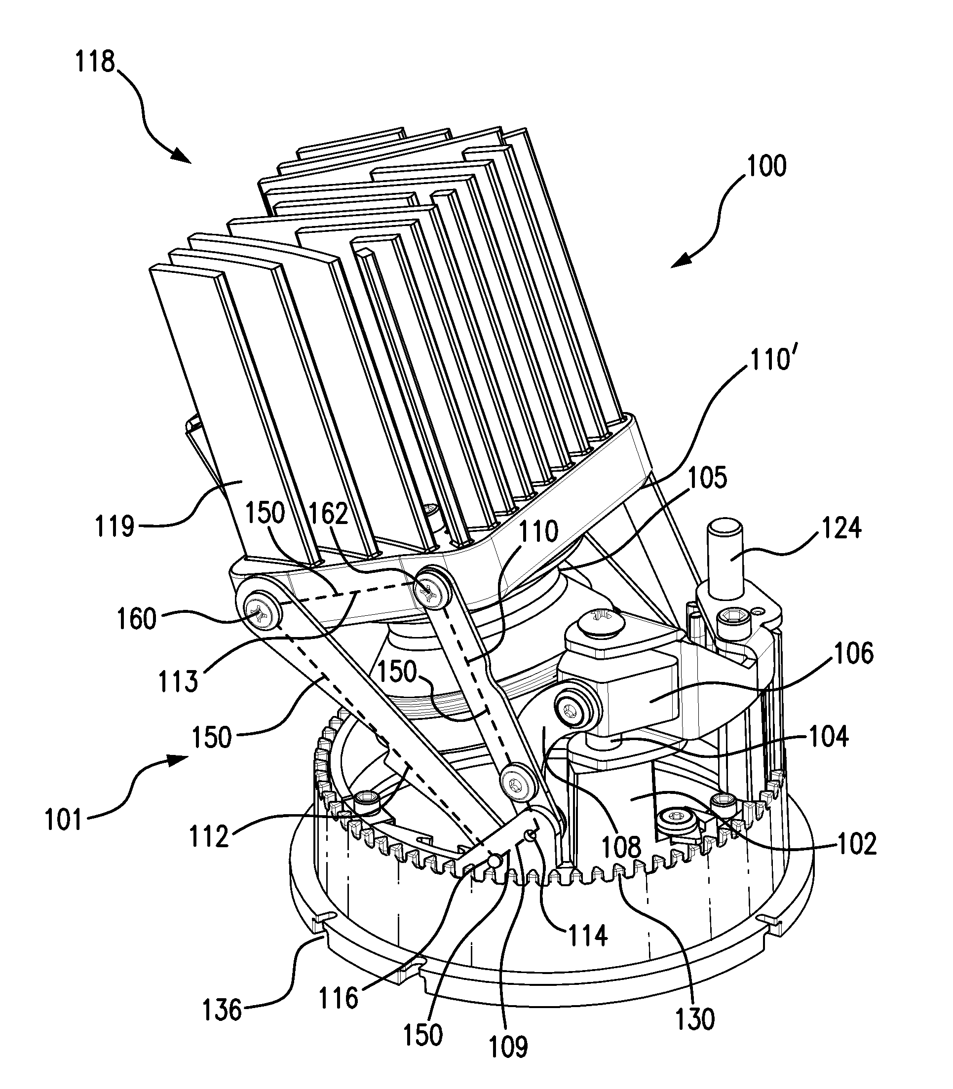
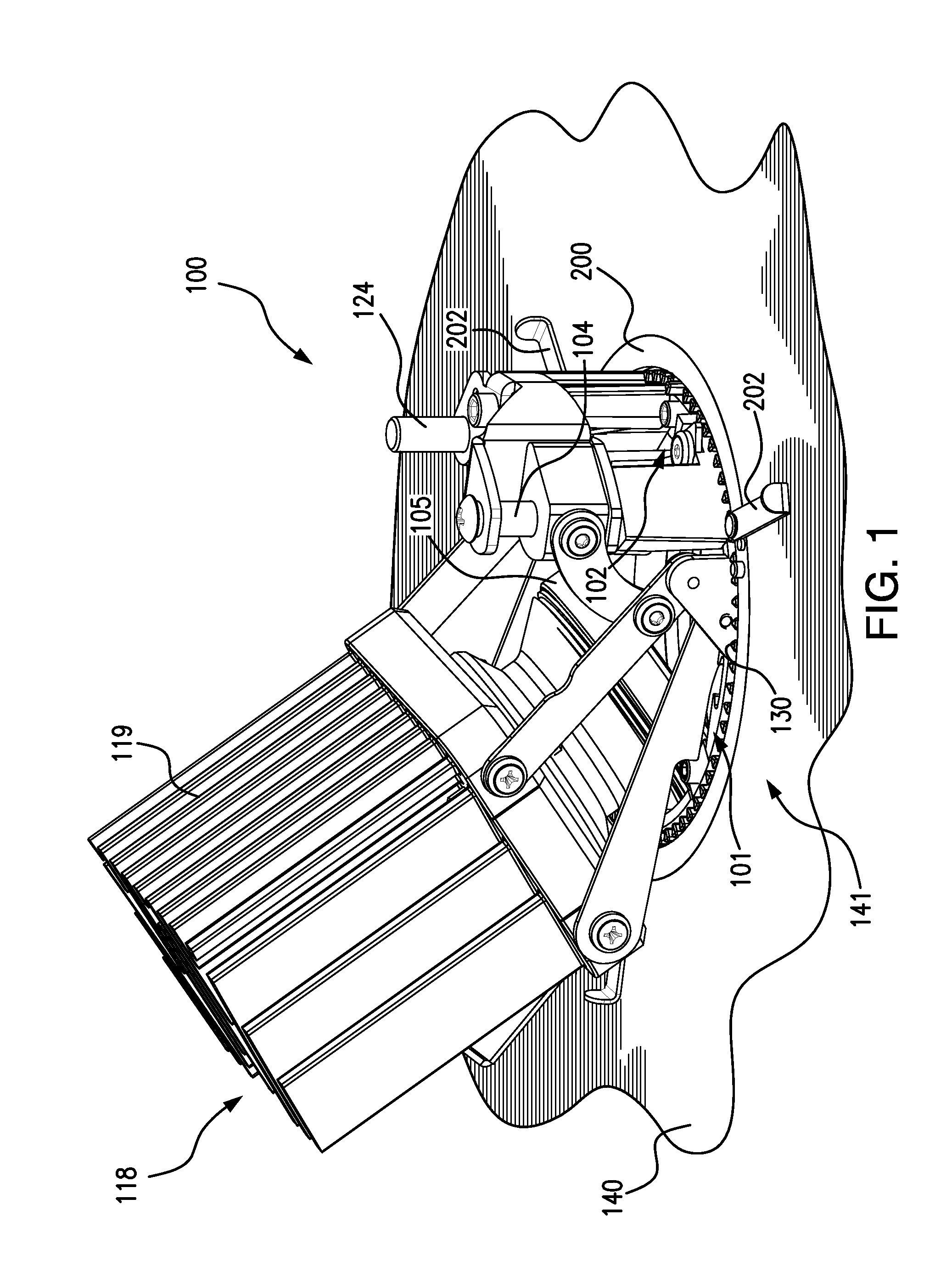
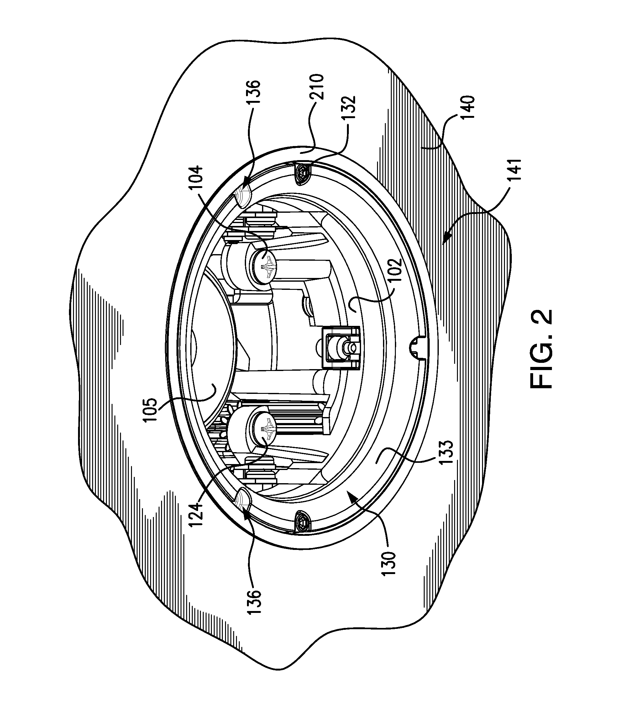
[0021]FIG. 1 is a top front perspective view from the right side, of an example adjustment mechanism for a directional recessed luminaire 100, mounted above a cutout opening 141 of a ceiling 140. The figure shows the adjustment mechanism for the directional recessed luminaire 100 mounted with an example remodel frame comprising an upper frame 200 for use in remodeling applications in non-insulated areas. Support levers 202 of the example upper frame 200 are shown overlapping the back surface of the ceiling 140 in the area of the back surface surrounding the cutout opening 141. The support levers 202 support the upper frame 200 in the cutout opening 141, which supports a stationary ring gear 130. A bearing ring 102 is positioned within the stationary ring gear 130 and is configured to rotate within the ring gear. The bearing ring 102 supports a four bar linkage adjustment mechanism 101. The four bar linkage adjustment mechanism 101 supports a lamp carrier frame 118 that includes a he...


PUM


Abstract

An adjustment mechanism for directional recessed luminaires includes a tilt adjustment screw 104 and rotation adjustment screw 124 supported in adjacent positions on a bearing ring 102, the screws being oriented vertically and conveniently accessible through an open center of the bearing ring. Follower 106 travels vertically on the tilt adjustment screw when rotated. Drive link 108 connected to both the follower and a four bar linkage (110), transfers force from the follower to the linkage when the tilt screw is rotated. The linkage pivots about anchor points 114,116 and is pivotally connected to lamp carrier frame 118 supporting light source 105. When the tilt adjustment screw is rotated, light source moves along a path (FIG. 6, 7) to aim the light beam. After aiming, the mechanism locks the light source into place. The mechanism is compact and the adjustment screws are easily accessible from beneath the mechanism.

Description

[0001]This patent application claims benefit under 35 U.S.C. 119(e), of the earlier filing date of U.S. Provisional Patent Application Ser. No. 61 / 945,346, filed Feb. 27, 2014.BACKGROUND OF THE INVENTION[0002]1. Field of the Invention[0003]The invention disclosed relates generally to luminaires and in particular to directional recessed luminaires.[0004]2. Discussion of the Related Art[0005]A luminaire is generally considered to be a complete lighting unit consisting of a lamp or lamps together with the parts designed to distribute the light, to position and protect the lamps, and to connect the lamps to the power supply. Recessed luminaires are generally installed into a hollow opening in a ceiling and are designed to be minimally visible from below. A trim ring typically surrounds the opening in the ceiling, to mask the opening, add aesthetic appeal, and help distribute the light in some configurations. Selecting lighting systems in the interior design of buildings requires conside...

Claims


Application Information

Patent Timeline
Patent Type & Authority Applications(United States)
IPC IPC(8): F21V21/14F21S8/02
CPCF21S8/026F21V21/14F21V21/30F21V21/04F21V21/041F21V21/047F21V21/26F21V21/28
Inventor FRYZEK, AARON P.
Owner ABL IP HLDG
Why Eureka
Try Eureka