Stand-by power estimating apparatus and program

Active Publication Date: 2015-09-03
PANASONIC INTELLECTUAL PROPERTY MANAGEMENT CO LTD
View PDF0 Cites 5 Cited by
  • Summary
  • Abstract
  • Description
  • Claims
  • Application Information

AI Technical Summary

Benefits of technology

[0023]According to the present invention, since a configuration is adopted which uses a transition with time of a plurality of used power amounts that are power amounts for respective measurement times and, when at least some of the plurality of used power amounts are

Problems solved by technology

In recent years, there has been an increase in electrical loads that consume a small amount of power even when not in use.
There

Method used


Image

  • Stand-by power estimating apparatus and program
  • Stand-by power estimating apparatus and program
  • Stand-by power estimating apparatus and program

Examples


Example

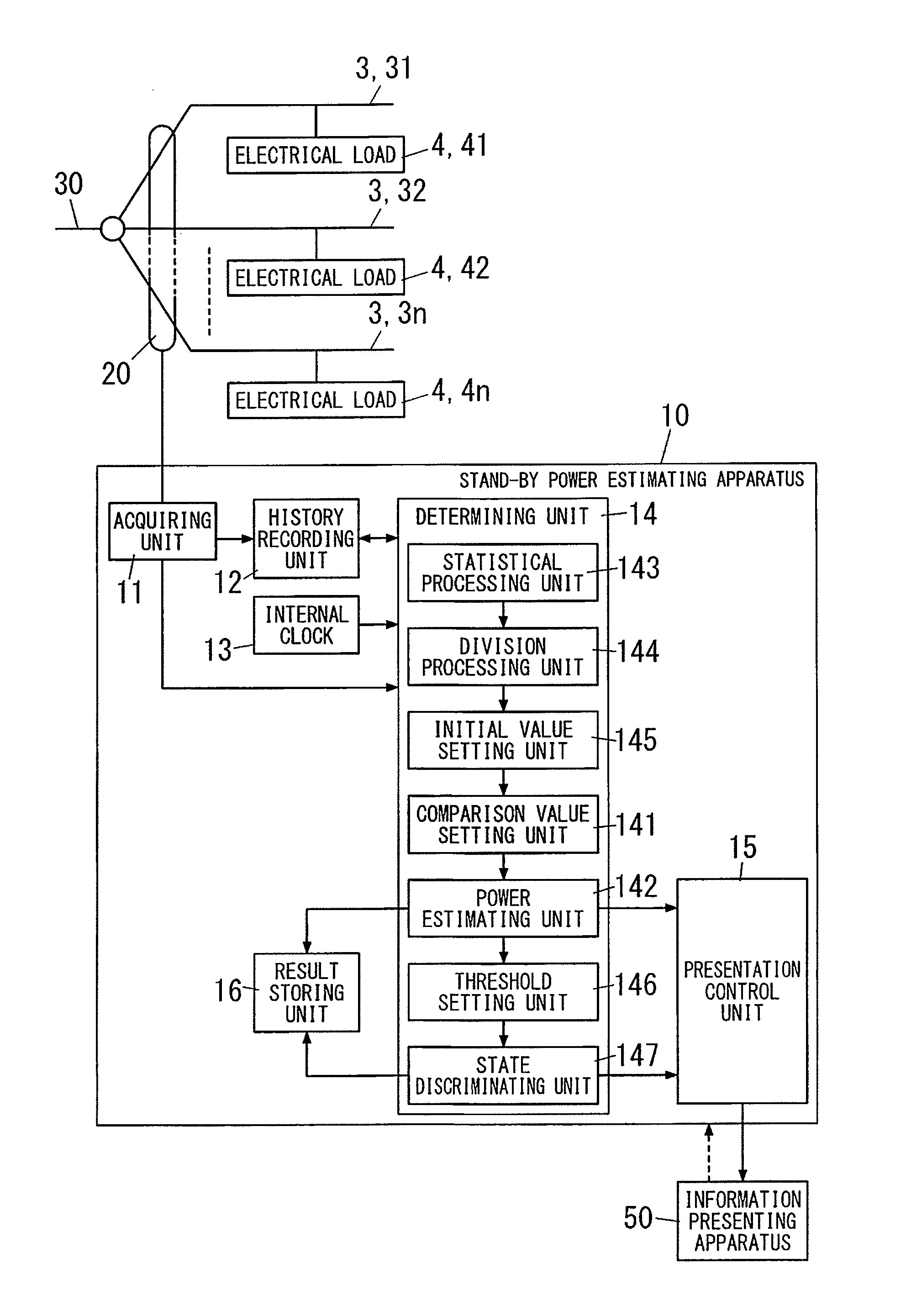
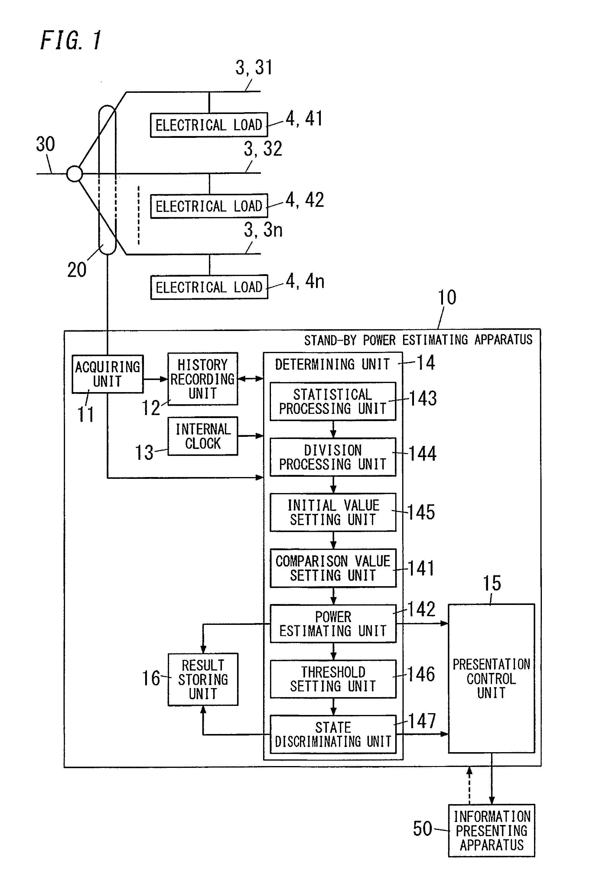
[0035]In the stand-by power estimating apparatus described below, each of a plurality of branch lines that branch off of a trunk line (a line passing through a main breaker) on a distribution panel installed at a consumer is assumed to constitute a segment of a power distribution network, whereby power is acquired for each branch line. However, the segment (measurement object, area) of the power distribution network can be set in various ways as necessary including the trunk line, lines that further branch off of the branch lines, outlets connected to the branch lines, and electrical loads connected to the branch lines.

[0036]As shown in FIG. 1, a trunk line 30 of the consumer branches off to a plurality of branch lines 31, 32, . . . on a distribution panel (not shown). The branch lines 31, 32, . . . respectively form lines that supply power in room units, lines that exclusively supply power to one electrical load 4, lines that supply power to a plurality of electrical loads 4 of a s...


PUM


Abstract

An estimating apparatus includes an acquiring unit, a history recording unit, and a determining unit. The acquiring unit acquires power amounts for respective measurement times from a measuring apparatus that measures power for each branch line, as a plurality of used power amounts. The history recording unit records the plurality of used power amounts in association with dates and times. The determining unit variably sets a comparison value for comparing magnitudes of the plurality of used power amounts recorded in the history recording unit, obtains a minimum value of the comparison value in a range satisfying a condition that an amount of time for which at least some of the plurality of used power amounts are continuously equal to or below the comparison value exceeds a prescribed sustained time, and estimates the minimum value to be a peak value of stand-by power of the branch line.

Description

TECHNICAL FIELD[0001]The present invention relates to a stand-by power estimating apparatus that estimates stand-by power of an electrical load, and a program that causes a computer to function as the stand-by power estimating apparatus.BACKGROUND ART[0002]In recent years, there has been an increase in electrical loads that consume a small amount of power even when not in use. Specifically, stand-by power occurs in various electrical loads including electrical loads that await wireless signals such as imaging equipment and lighting fixtures, electrical loads that stand by for signal reception or perform signal transmission when unused such as communication devices, and electrical loads that run an internal clock when unused. In addition, some electrical loads such as television receivers and personal computers enable operating modes such as a stand-by mode and a power saving mode to be selected. In these operating modes, electrical loads enter an unused state without having their po...

Claims


Application Information

Patent Timeline
IPC IPC(8): G06F1/28G06F11/30
CPCG06F1/28G06F11/3024G06F11/3055H02J9/005H02J13/00H02J13/00004H02J2310/14Y02B70/30Y02B70/3225Y04S20/20Y04S20/222Y04S20/242G01R21/00G01R22/00
Inventor SHIMIZU, NORIYOSHINISHIYAMA, TAKASHI
Owner PANASONIC INTELLECTUAL PROPERTY MANAGEMENT CO LTD
Why Eureka
Try Eureka