Surgical knife and tools adapted for simplified blade removal

a technology of surgical blades and tools, applied in the field of surgical scalpels, can solve the problems of unstable blade support, easy sliding of the blade, and large bulky tools that allow single-handed operation, and achieve the effect of facilitating the sliding removal of the blade and flexing the blad

Active Publication Date: 2015-09-10
SCALPAL LLC
View PDF6 Cites 0 Cited by
  • Summary
  • Abstract
  • Description
  • Claims
  • Application Information

AI Technical Summary

Benefits of technology

[0018]The invention provides a modified scalpel that lends itself more easily to removal of the blade while significantly reducing the wobble that characterizes known designs.
[0020]The knife includes a handle having a mount for affixing the blade. The mount has a concave surface supporting an elongate protrusion for engaging a complementary slot in the blade, the concave surface reaching a landing located sufficiently rearward of the tip so as to remain exposed when the blade is mounted on the handle with a surface of the blade being completely supported by said concave surface. The concave surface induces slight flexing of the blade, which creates tension that urges the front of the blade upward against the shoulder, thereby securing the blade on the handle.
[0021]A channel in the landing is dimensioned such that a rearmost part thereof remains exposed when the blade is mounted on the handle, thereby allowing the blade to be removed by inserting a curved lever into the channel underneath a rearmost part of the blade and swiveling the lever so as to lift a rear portion of the blade and facilitate its sliding removal from the elongate protrusion.
[0022]The blade removal tool may be adapted for use with the scalpel according to the invention or may be adapted for use with conventional scalpels. In either case, the removed blade is retained inside the receptacle which may be safely disposed of outside the operating theater, thus avoiding the current tendency to collect multiple used blades often from different patients in a central garbage dispenser, which is located in the operating theater and serves as a hive of bacteria prior to its eventual disposal.

Problems solved by technology

This can be difficult, particularly when the scalpel is wet.
With the ever increasing spread of blood transmitted diseases, the removal is also a dangerous procedure as any accidental injury from the blade can have life-threatening ramifications.
Tools that allow single-handed operation appear generally to be bulky and often to require anchoring in some way.
However, it has been found that this is prone to a number of disadvantages.
First, in use the blade is not supported by the tang over its entire surface and the narrower the tang the more pronounced this is, leading to unstable support of the blade.
This is undesirable and militates against precise control of the blade, which is clearly a prerequisite for fine surgical procedures.

Method used


Image

  • Surgical knife and tools adapted for simplified blade removal
  • Surgical knife and tools adapted for simplified blade removal
  • Surgical knife and tools adapted for simplified blade removal

Examples


first embodiment

[0035]FIGS. 9 and 10 are pictorial representations showing details of a blade removal tool 40 for removing a blade from the surgical scalpel 10 having an elongate channel 25 as described above with reference to FIGS. 1 to 8. The blade removal tool 40 comprises a generally closed receptacle 41 having an opening 42 to which a resilient shutter 43 is hinged at a lower edge for pivotally opening about a hinge axis shown as 44. An upper edge of the opening 42 curves inwardly, having a claw 45 that points inside the receptacle 41 towards its closed end and is dimensioned such that it is accommodated within the elongate channel 25.

[0036]Upon insertion of the scalpel 10 into the opening 42 of the blade removal tool 40, the shutter 43 is resiliently pushed inward. The scalpel 10 is inserted until the channel 25 becomes aligned with the claw 45, whereupon lifting the scalpel upward at its front tip urges the channel 25 into upward engagement with the claw 45 behind the rear edge of the blade...

second embodiment

[0038]FIGS. 11 to 14 are pictorial representations showing details of a blade removal tool 50 for removing a blade from a conventional surgical scalpel shown as 100 as described in the background. The blade removal tool 50 comprises a generally closed receptacle 51 having an opening 52 to which a resilient shutter (not shown) is hinged at a lower edge. Attached to an inner side surface of the receptacle 51 is a claw 55 that is shown enlarged in FIG. 14 where it is seen that the claw 55 is directed laterally from the inner wall of the receptacle 51 supporting the claw to the opposite wall.

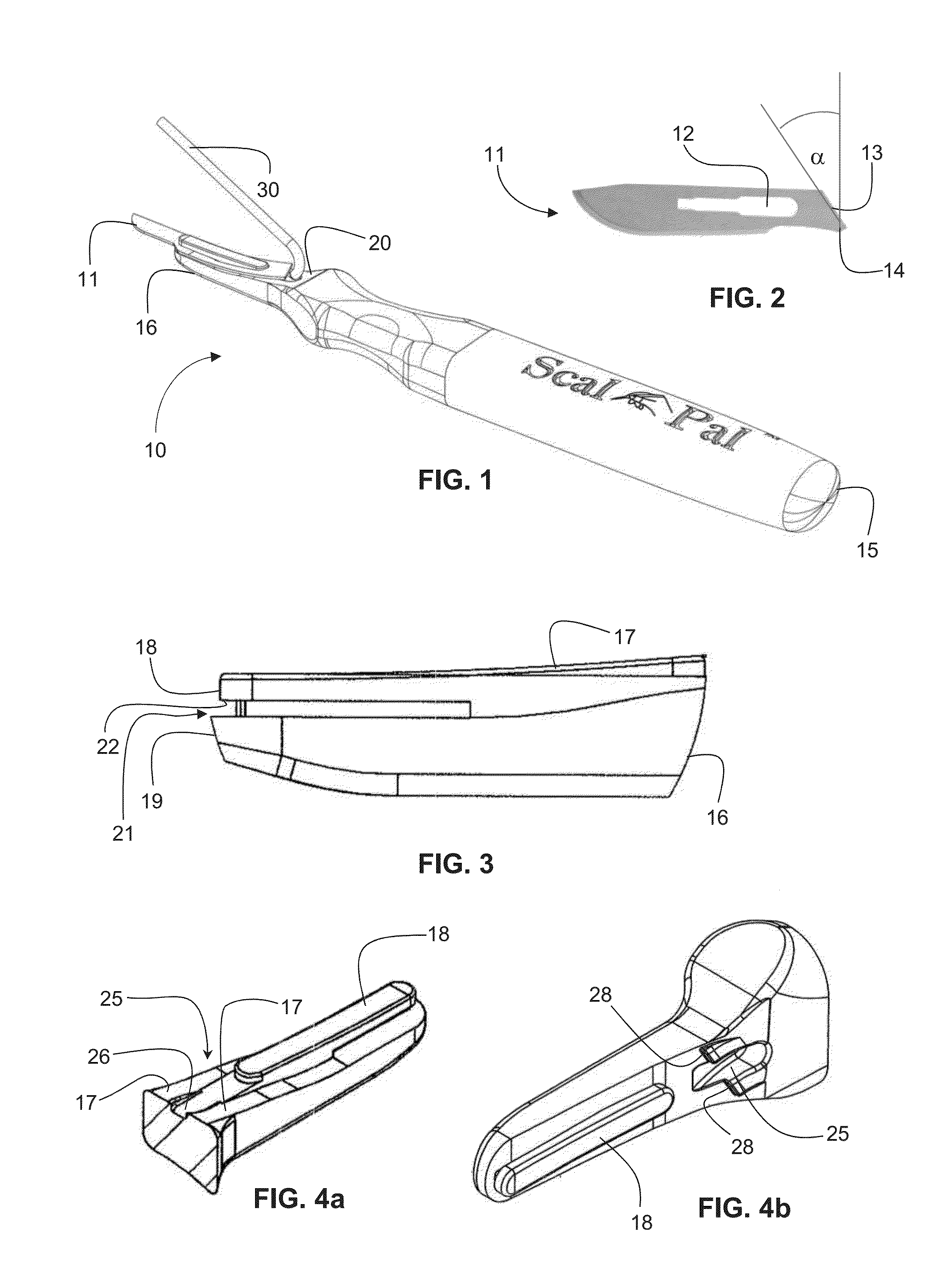
[0039]In use, the scalpel 100 is inserted into the opening 52 of the blade removal tool 50 below the claw 55, whereby the shutter is resiliently pushed inward. As noted above with reference to FIG. 2, the rear edge 13 of the blade is inclined at an acute angle α the vertical, thus creating a corner 14 that overhangs the mount. The scalpel is inserted until the corner 14 engages the outwardly protru...


PUM


Abstract

A knife (10) has a handle (15) with a mount (16) for affixing a removable blade (11). A concave surface (17) of the mount supports an elongate protrusion (18) for engaging a complementary slot (12) in the blade and reaches a landing (20) rearward of the tip that is exposed when the blade is mounted on the handle with a surface of the blade being completely supported by the concave surface. A channel (25) in the landing is dimensioned such that a rearmost part (26) thereof remains exposed when the blade is mounted on the handle. The blade is removed by inserting a curved lever (30) into the channel underneath a rearmost part of the blade and swiveling the lever so as to disengage the blade from the elongate protrusion.

Description

FIELD OF THE INVENTION[0001]This invention relates to surgical scalpels.BACKGROUND OF THE INVENTION[0002]A conventional surgical scalpel comprises a reusable handle having a tang at one end on which a replaceable slotted blade is mounted. The handle is intended to be used repeatedly, but the blade is normally discarded after each instance of use. Some operations may require several blades to be used successively on the same handle, e.g. where the blades become dull or contaminated, or a different style of blade is required at different stages of the operation.[0003]To remove the blade from the handle, the heel portion of the slotted blade shown in FIG. 1 must be bent out of its plane (i.e. transversely to the handle), and then moved axially along the tang so that the heel portion rides over the tang thereby releasing the tang from the slot. The slot is of keyhole shape, which as seen in the figure is wider at the rear than at the front so as to facilitate partial insertion of the ta...

Claims


Application Information

Patent Timeline
Patent Type & Authority Applications(United States)
IPC IPC(8): A61B17/3213A61B17/3217
CPCA61B17/3213A61B2017/32116A61B17/3217
Inventor GITMAN, ELIOT ROBERT
Owner SCALPAL LLC
Why Eureka
Try Eureka