Micro-channel device

a microchannel device and microchannel technology, applied in the direction of positive displacement liquid engine, laboratory glassware, instruments, etc., can solve the problems of reaction product emission, reaction product not being produced, and the quantity of liquid that a microchannel device can contain is very small

Inactive Publication Date: 2015-09-10
CANON KK
View PDF4 Cites 20 Cited by
  • Summary
  • Abstract
  • Description
  • Claims
  • Application Information

AI Technical Summary

Benefits of technology

[0017]The present invention provides a device designed to eliminate bubbles of various different sizes that have intruded into the liquid that is running through a micro-channel from the micro-channel and prevent bubbles from intruding into the reaction region and the optical examination region in the device.
[0019]Thus, according to the present invention, the bubbles that intrude into the micro-channel are caught at the gas-liquid interface in the bubble trapping region and merged with the gas-liquid interface. The gas that constitutes the bubbles is discharged by way of the air passage formed at the bubble trapping region and hence no bubbles will be released back into the micro-channel from the gas-liquid interface. Then, as a result, bubbles can reliably be eliminated from the flow channel regardless of the sizes and the volumes of the bubbles trapped in the bubble trapping region and therefore are prevented from intruding into the reaction region and the optical examination region of the device.

Problems solved by technology

If compared with conventional desk top equipment, the quantity of the liquid that a micro-channel device can contain is very small.
Particularly, when one or more than one bubbles are allowed to intrude into a micro-channel such as a reaction zone of a PCR device, a problem of temperature unevenness arises so that the intended reaction product may not be produced.
Besides, if one or more than one bubbles are allowed to intrude into the optical sensor section of the micro-channel device, the bubbles hinder the emission of fluorescence so that the spectral intensity may not accurately be observed.
However, with the structure of the above-cited patent document, when bubbles are allowed to continuously intrude into the flow channel, the bubbles keep on remaining in the trap and the trap will eventually be saturated with bubbles.
Once the trap becomes saturated with bubbles, the structure can no longer eliminate bubbles.

Method used


Image

  • Micro-channel device
  • Micro-channel device
  • Micro-channel device

Examples


example 1

[0062]Now, the present invention will be described further in greater detail by way of examples. Micro-channel devices were prepared in the examples that will be described below by applying the arrangement described above for the embodiments.

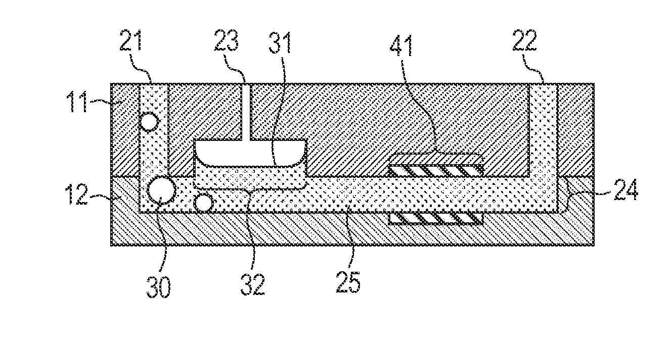
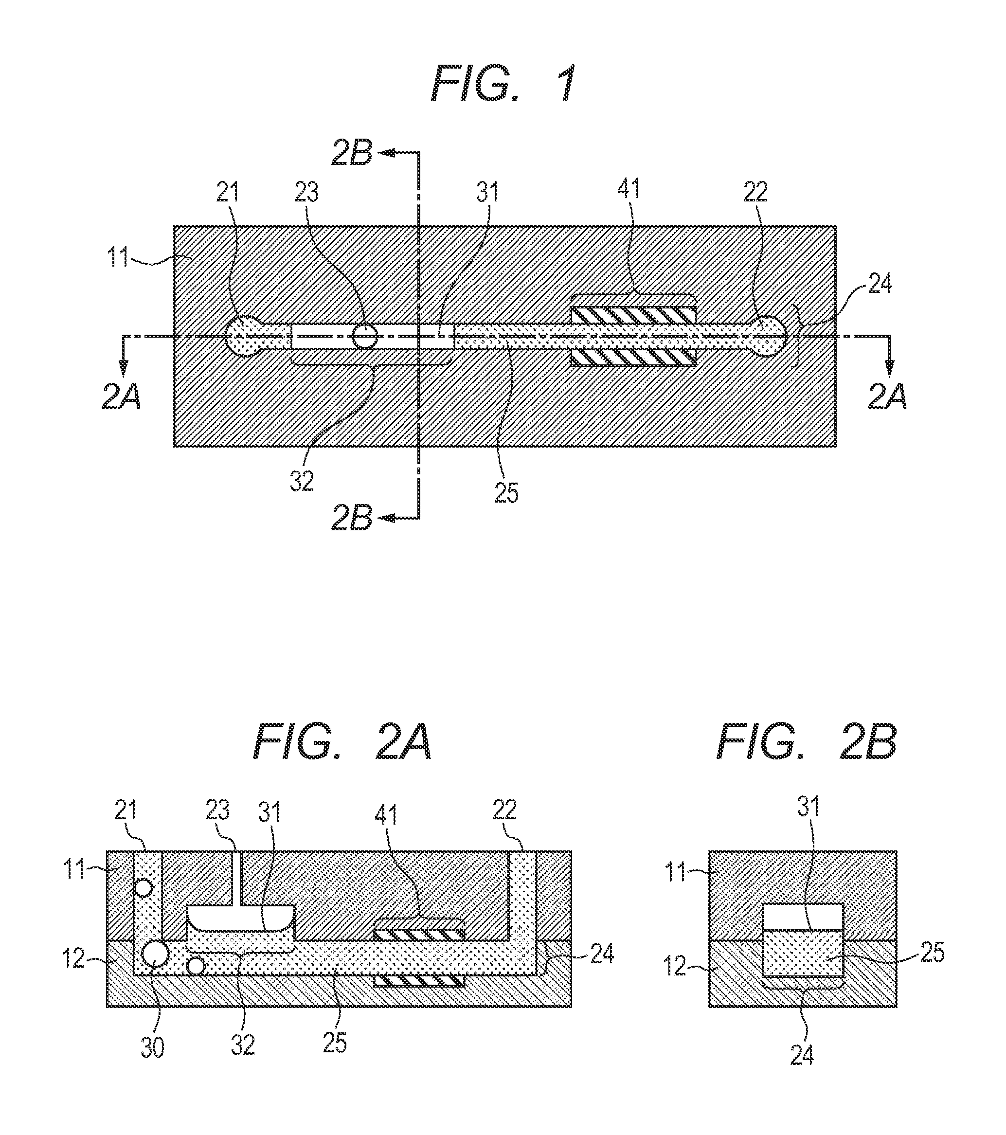
[0063]Quartz substrates were brought in as the material of the substrates to be used in this example and substrates having respective profiles as illustrated in FIGS. 1, 2A and 2B were obtained. Each of the substrates had a width of 60 mm, a depth of 30 mm and a thickness of 0.6 mm. The obtained substrates included the second substrate 12 having a groove (horizontal width: 180 μm, vertical width: 20 μm) that eventually became a micro-channel 24 and the first substrate 11 having a liquid injection port 21 (diameter: 0.35 mm), a liquid discharge port 22 (diameter: 0.35 mm), a recess (horizontal width: 180 μm, vertical width: 80 μm, length: 5 mm) that eventually became a bubble trapping region 32 and had a profile matching the profile of the groove...

example 2

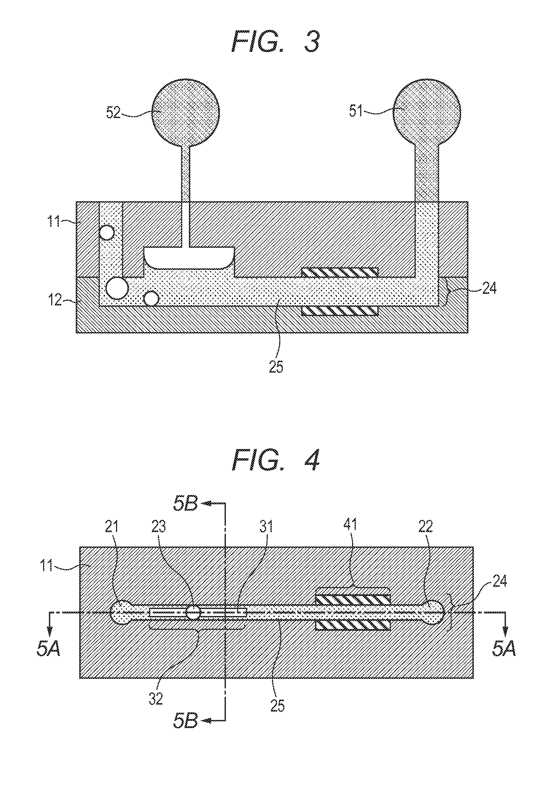
[0071]Quartz substrates were brought in as the material of the substrates to be used in this example and substrates having respective profiles as illustrated in FIGS. 4, 5A and 5B were obtained by dry etching. Each of the obtained substrates had a width of 60 mm, a depth of 30 mm and a thickness of 0.6 mm. The obtained substrates included the second substrate having a groove 24 (horizontal width: 180 μm, vertical width: 20 μm) that eventually became a micro-channel and the first substrate 11 having a liquid injection port 21 (diameter: 0.35 mm), a liquid discharge port 22 (diameter: 0.35 mm) and a gas passage 23 (diameter: 0.35 mm).

[0072]The bubble trapping region (horizontal width: 180 μm, vertical width: 80 μm, length: 3 mm) having a profile of running along the groove of the second substrate was made to represent a triangular cross section that was tapered in the height direction as illustrated in FIG. 5B by wet etching so as to produce a gas-liquid interface in an apex part of t...

example 3

[0075]Quartz substrates were brought in as the material of the substrates to be used in this example and substrates having respective profiles as illustrated in FIGS. 6, 7A and 7B were obtained by dry etching. Each of the obtained substrates had a width of 60 mm, a depth of 30 mm and a thickness of 0.6 mm. The substrates included the second substrate having a groove 24 (horizontal width: 180 μm, vertical width: 20 μm) that eventually became a micro-channel and the first substrate 11 having a liquid injection port 21 (diameter: 0.35 mm), a liquid discharge port 22 (diameter: 0.35 mm) and a gas passage 23 (diameter: 0.35 mm).

[0076]The bubble trapping region (horizontal width: 180 μm, length: 3 mm) having a profile of running along the groove of the second substrate was made to represent a sloped cross section such that the height of the bubble trapping region 32 increased toward the downstream side by drilling so as to produce a gas-liquid interface 31 in an apex part of the sloped cr...


PUM

PropertyMeasurementUnit
widthaaaaaaaaaa
widthaaaaaaaaaa
depthaaaaaaaaaa

Abstract

A micro-channel device has a micro-channel for flowing liquid therethrough and includes a first aperture held in communication with the micro-channel for the purpose of injecting liquid, a second aperture held in communication with the micro-channel for the purpose of discharging liquid and a bubble trapping region constituting a part of the micro-channel. The height of the bubble trapping region is greater than the height of the micro-channel at the position of liquid inflow into the micro-channel located downstream relative to the bubble trapping region.

Description

BACKGROUND OF THE INVENTION[0001]1. Field of the Invention[0002]The present invention relates to a micro-channel device.[0003]2. Description of the Related Art[0004]A variety of devices and sensors have been and are being developed in order to acquire the information on the processes of biochemical reactions and the results of chemical analyses. Micro-devices having a micro-structure such as a micro-channel having a predetermined flow channel profile that is formed in two or more than two substrates have been proposed as such devices. Such micro-devices can be further downsized because they can be manufactured by utilizing semiconductor manufacturing techniques and other relevant techniques. Furthermore, such micro-devices allow all the analytical process down to acquiring desired information to be executed on the micro-device.[0005]A device of the above-identified type is referred to as a micro total analysis system (μ-TAS) or a lab-on-a-chip. Particularly, a device having a micro-...

Claims


Application Information

Patent Timeline
Patent Type & Authority Applications(United States)
IPC IPC(8): B01L3/00
CPCB01L3/502723B01L2400/0475B01L2200/0684B01L3/50273B01L2200/146B01L2300/0816B01L2400/0487
Inventor SAITO, TOMOHIRO
Owner CANON KK
Why Eureka
Try Eureka