Eureka AIR delivers breakthrough ideas for toughest innovation challenges, trusted by R&D personnel around the world.

Imprint apparatus, alignment method, and method of manufacturing article

Active Publication Date: 2015-09-10
CANON KK
View PDF1 Cites 3 Cited by
  • Summary
  • Abstract
  • Description
  • Claims
  • Application Information

AI Technical Summary

Benefits of technology

The present invention is about an imprint apparatus that uses a mold to create patterns on a substrate. It includes a stage for holding the substrate, a mechanism for holding the mold, a scope to find a mark on the mold, a mechanism to move the scope to position it correctly, a processing unit to calculate the amount of movement needed to align the mold and substrate, and a driving mechanism to move the scope. This invention makes the process of aligning the mold and substrate faster and easier.

Problems solved by technology

The position of the mold also needs to be obtained in advance in the global alignment scheme because a positional shift in the mold when bringing the resin on the substrate and the mold into contact with each other leads to a decrease in overlay accuracy.
Such prealignment of the mold takes much time, and thus becomes a factor to reduce the throughput of the imprint apparatus.
Particularly, in the imprint apparatus, in addition to the need to change molds regularly, a shift in the alignment mark on the mold is large and thus the alignment mark on the mold easily falls outside the field of view of the alignment scope.

Method used


Image

  • Imprint apparatus, alignment method, and method of manufacturing article
  • Imprint apparatus, alignment method, and method of manufacturing article
  • Imprint apparatus, alignment method, and method of manufacturing article

Examples


Embodiment Construction

[0015]Preferred embodiments of the present invention will be described below with reference to the accompanying drawings. Note that the same reference numerals denote the same members throughout the drawings, and a repetitive description thereof will not be given.

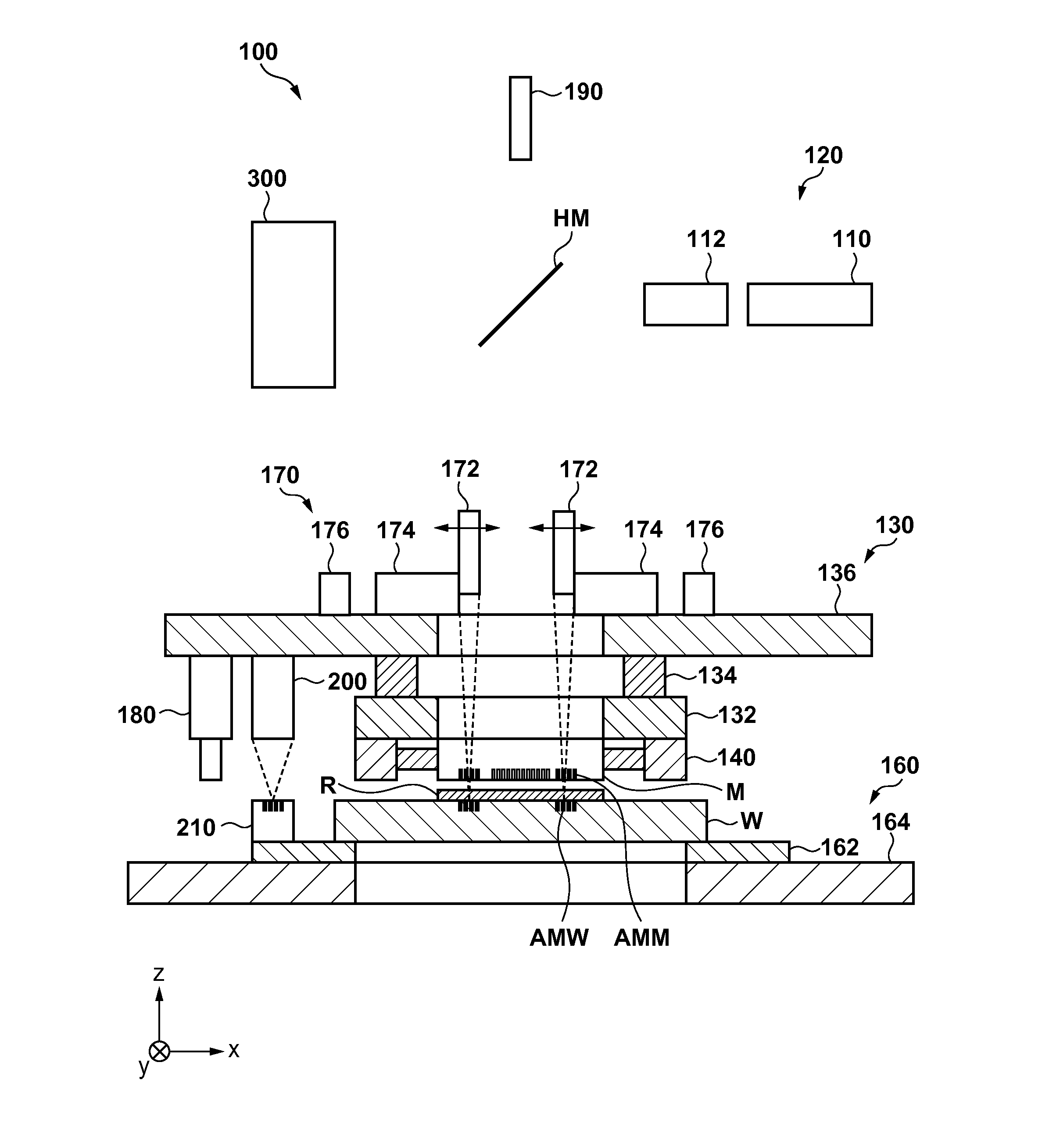
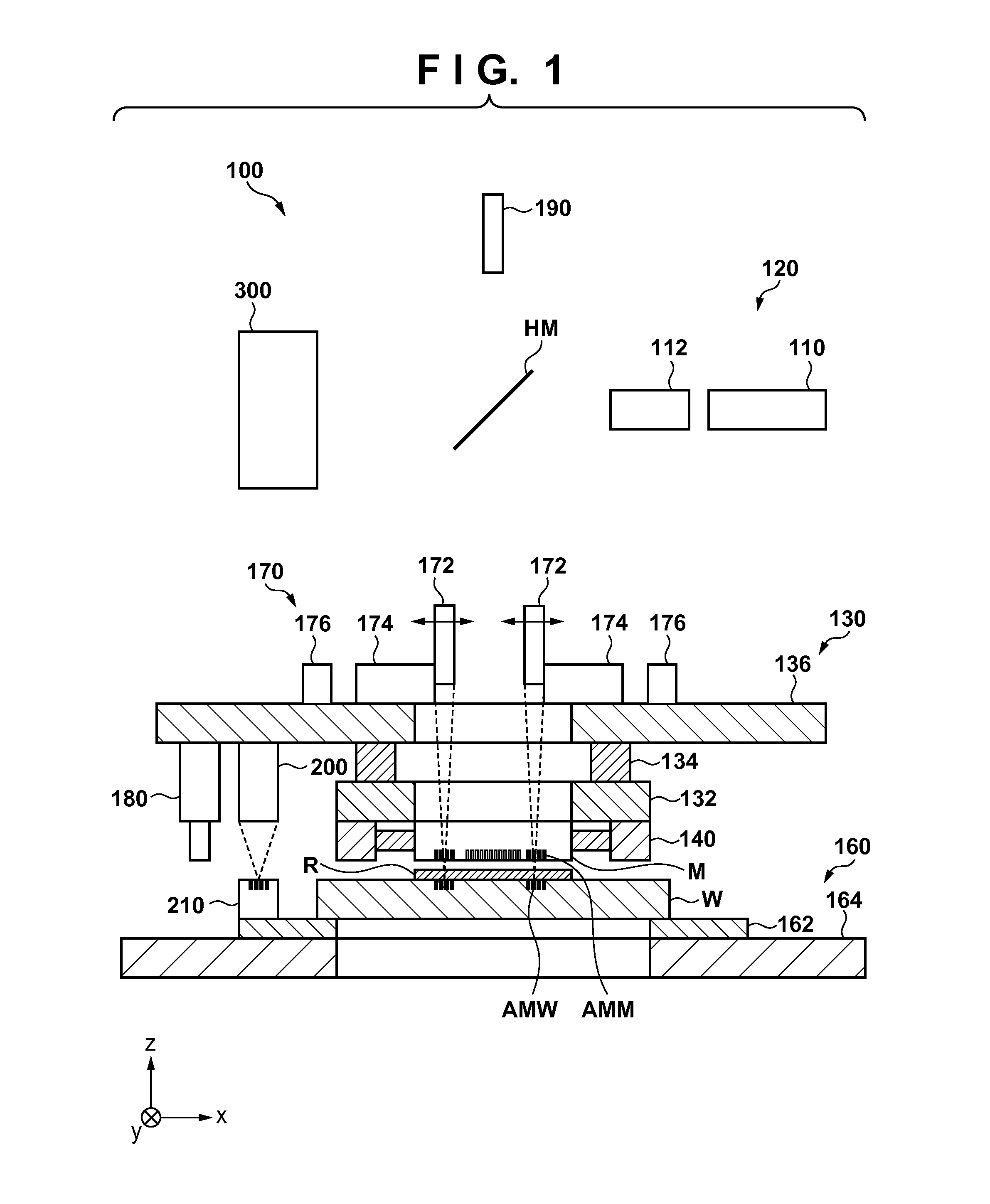
[0016]FIG. 1 is a schematic view showing the arrangement of an imprint apparatus 100 according to an aspect of the present invention. The imprint apparatus 100 is a lithography apparatus which molds an imprint material on a substrate using a mold and forms a pattern on the substrate. In this embodiment, the imprint apparatus 100 uses a resin as the imprint material and adopts, as a resin-curing method, a photo-curing method in which the resin is cured by irradiation with ultraviolet light (UV light). However, the imprint apparatus 100 may also cure the resin by irradiation with light having another wavelength region, and may also adopt a heat-curing method in which the resin is cured by using another energy such as heat.

[00...


PUM


Abstract

The present invention provides an imprint apparatus which forms a pattern in an imprint material on a substrate using a mold, the apparatus including a stage configured to hold the substrate, a holding mechanism configured to hold the mold, a scope configured to detect a mark provided on the mold, a driving mechanism configured to drive the scope, and a processing unit configured to position the scope by the driving mechanism so that the scope detects the mark on the mold held by the holding mechanism, obtain a positional shift amount from a reference position of the mold held by the holding mechanism based on a driving amount of the scope that has been required for positioning the scope, and performs alignment between the mold and the substrate based on the positional shift amount.

Description

BACKGROUND OF THE INVENTION[0001]1. Field of the Invention[0002]The present invention relates to an imprint apparatus, an alignment method, and a method of manufacturing an article.[0003]2. Description of the Related Art[0004]An imprint technique can form a fine pattern, and is coming into practical use as one of lithography techniques for volume production of magnetic storage media and semiconductor devices. As disclosed in Japanese Patent No. 4185941, an imprint apparatus which employs the imprint technique forms a pattern on a substrate such as a silicon wafer or a glass plate using a mold (die), as an original, on which a fine pattern (unevenness) has been formed. The imprint apparatus, for example, coats the substrate with a light curable resin (for example, an ultraviolet-curing resin), and molds the resin using the mold. The resin is irradiated with light (for example, ultraviolet light) to be cured, and then the mold is separated from the cured resin, thereby forming the pat...

Claims


Application Information

Patent Timeline
IPC IPC(8): B29C59/02B29C59/00
CPCB29C59/02B29L2007/001B29C59/002G03F7/0002G03F9/7088
Inventor USUI, YOSHIYUKI
Owner CANON KK
Why Eureka
Eureka Blog
Learn More