Sliding door of machine tool

a technology of sliding door and machine tool, which is applied in the direction of mechanical equipment, manufacturing tools, wing accessories, etc., can solve the problems of inability to increase the opening width of the door, interfere with each other, and increase the overall thickness, so as to achieve the effect of increasing the door opening width

Active Publication Date: 2015-09-10
FANUC LTD
View PDF11 Cites 7 Cited by
  • Summary
  • Abstract
  • Description
  • Claims
  • Application Information

AI Technical Summary

Benefits of technology

[0015]According to the present invention, there can be provided a slidin

Problems solved by technology

Possibly, therefore, the door may interfere with an installation space for mechanism sections, such as a movable cover, saddle, etc., of the machine tool so that the opening width of the door cann

Method used


Image

  • Sliding door of machine tool
  • Sliding door of machine tool
  • Sliding door of machine tool

Examples


Embodiment Construction

[0023]A conventional technique related to a sliding door of a machine tool and its problems will be described first.

[0024]An example of a guide structure of the sliding door of the machine tool according to the conventional technique will first be described with reference to FIGS. 6A and 6B. FIGS. 6A and 6B show an open state and a closed state, respectively, of the door.

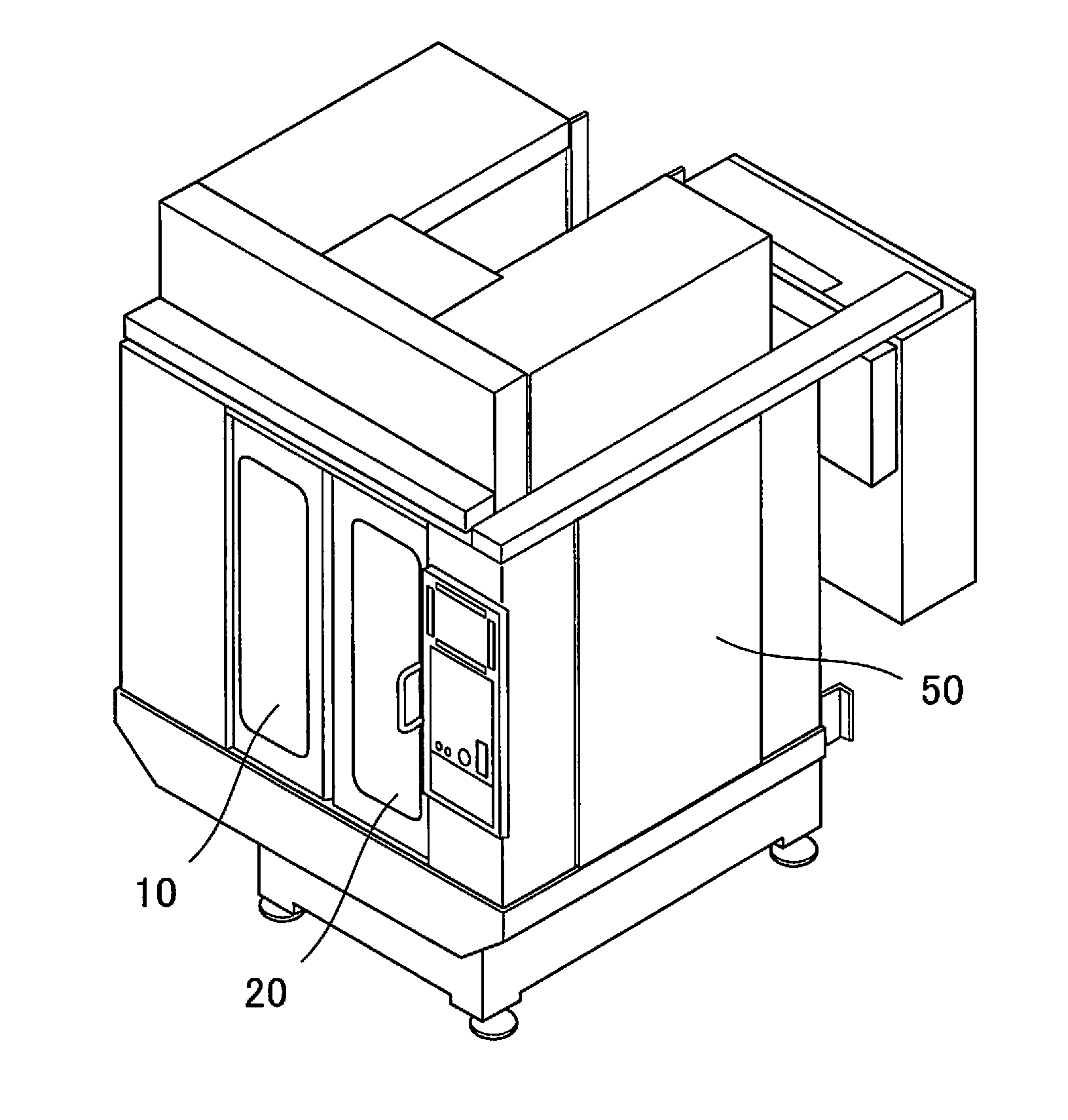
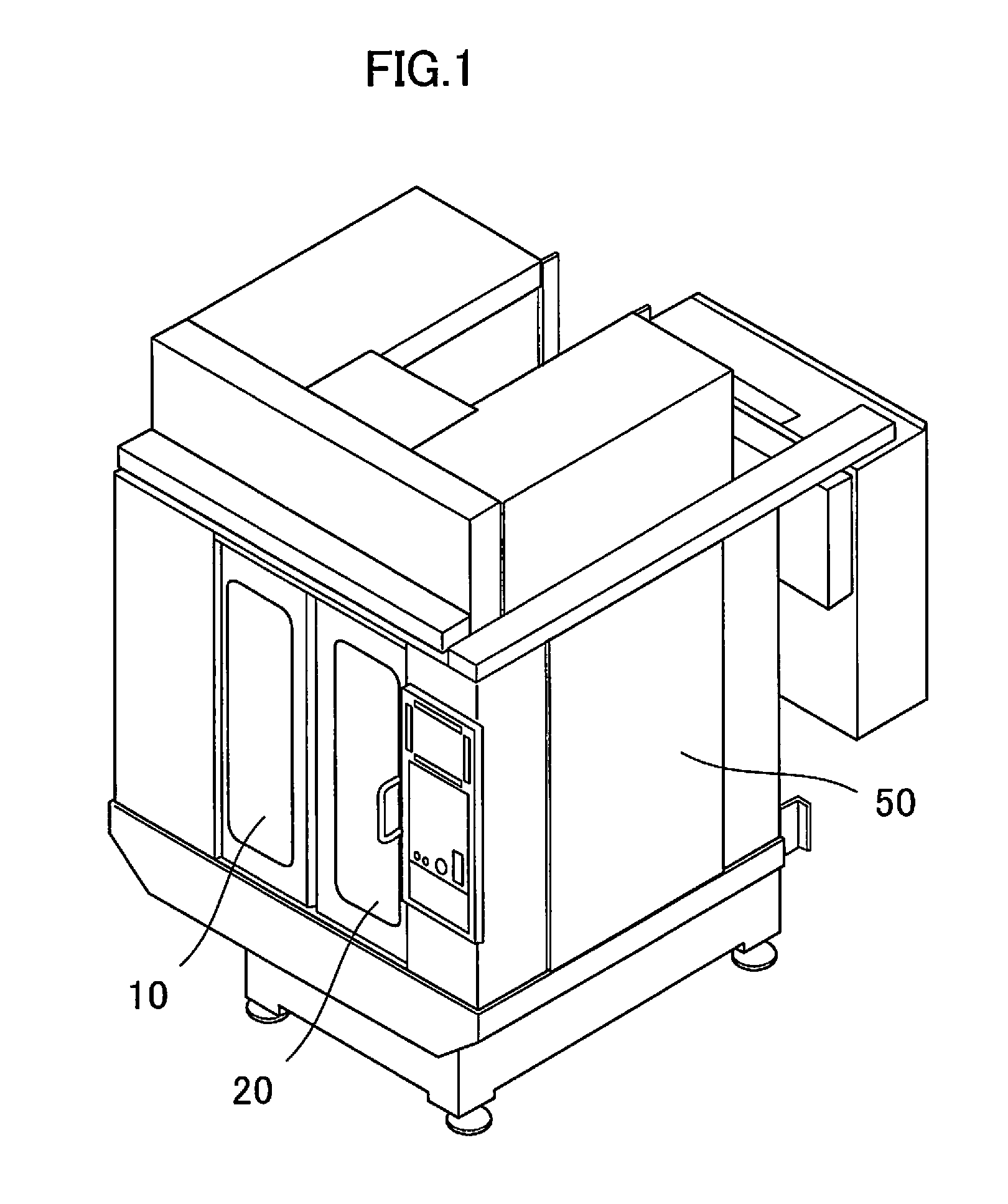
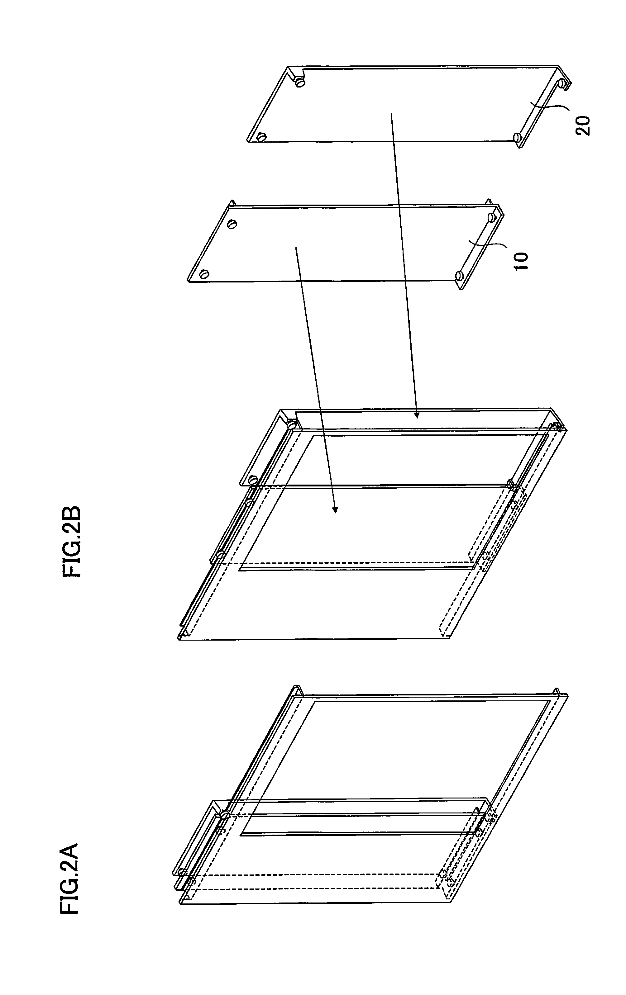
[0025]As shown in FIG. 6B, the sliding door comprises a first door 110 and a second door 120, both of which are slidable. When the sliding door is in the open state, as shown in FIG. 6A, the first and second doors 110 and 120 overlap each other to leave an opening 200 through which a workpiece (not shown) to be machined can be loaded into and unloaded from the machine tool. When the sliding door is in the closed state, in contrast, the first and second doors 110 and 120 hardly overlap each other so that the opening 200 is closed, as shown in FIG. 6B.

[0026]A structure in the vicinity of guide means of the prior art s...


PUM


Abstract

In a sliding door disposed in an opening of a cover surrounding a machine tool,
From among two adjacent door panels, at least one of sliding members of the door panel which is located closer to a door frame slides on a door frame guide track, whereas at least one of sliding members of the door panel which is located farther from the door frame slides on the door frame guide track, and at least one of the remaining sliding members slides on the door panel guide track. Thus, guide means can be prevented from projecting vertically.

Description

BACKGROUND OF THE INVENTION[0001]1. Field of the Invention[0002]The present invention relates to a sliding door of a machine tool, and more particularly, to a guide structure of a sliding door.[0003]2. Description of the Related Art[0004]A machine tool has a machining space in which a workpiece is placed and machined. In machining the workpiece, a cover may sometimes be provided to protect the workpiece itself and prevent chips produced during the workpiece machining and a coolant from scattering to the surrounding area.[0005]FIG. 1 is a perspective view of an entire machine tool. The machine tool is provided therein with a machining space in which a workpiece (not shown) can be placed and its side surfaces are covered by a cover 50. Further, first and second slide-type doors 10 and 20 for workpiece loading / unloading and the like are arranged on the front side of the machine tool. In this machine tool, a two-tiered sliding door is used in order to handle large workpieces.[0006]Japan...

Claims


Application Information

Patent Timeline
IPC IPC(8): E05D15/06E06B5/00E06B1/04
CPCE05D15/0652E06B5/00E06B1/04E05D15/0656B23Q11/0825E05D15/08E05Y2201/684E05Y2600/46E05Y2900/608F16P1/02B23Q11/0891
Inventor INAGUCHI, YUUZOU
Owner FANUC LTD
Why Eureka
Try Eureka