Bush for isolating stabilizer from vibration

a stabilizer and bush technology, applied in the field of bush, can solve the problems of axle beam and stabilizer bar subjected to some vibration, and achieve the effect of suppressing deformation, suppressing the bush for isolating the stabilizer, and effectively preventing the bush from coming

Active Publication Date: 2014-03-18
HONDA MOTOR CO LTD
View PDF9 Cites 2 Cited by
  • Summary
  • Abstract
  • Description
  • Claims
  • Application Information

AI Technical Summary

Benefits of technology

[0015]In the present invention, when the opening engages with the stabilizer bar, the pair of second projections is the first to come into contact with the stabilizer bar. This causes elastic deformation which opens the opening on the open end side approximately halfway. Afterwards, the pair of first projections come into contact with the stabilizer bar. This causes elastic deformation which opens the opening on the fitting hole side approximately halfway. Because the opening can be opened in two stages, the force used to open the opening (i.e., the force occurring when the opening engages with the stabilizer bar) is unexpectedly small. As a result, the bush for isolating the stabilizer from vibration can be fitted onto the stabilizer bar using a small amount of force. Also, an improvement is realized in regard to the bush for isolating the stabilizer from vibration being attached to the axle beam and the stabilizer bar.
[0016]When the fitting hole has been fitted over the stabilizer bar, the elastic element comes into contact with the substantially U-shaped inner surface of the axle beam and is elastically deformed in the direction closing the opening. This elastic deformation causes the pair of second projections to make contact with the pair of first projections. As a result, the pair of first projections adjacent to the fitting hole and the pair of second projections adjacent to the open end of the opening come into contact with each other when the fitting hole has been fitted over the stabilizer bar. The pair of first projections and the pair of second projections support each other so that any force acting on the other is stopped. For example, when force occurs in the direction for extracting the fitting hole from the stabilizer bar (extraction force), the extraction force causes elastic deformation which moves the pair of first projections toward the pair of second projections. However, because the pair of first projections is supported by the pair of second projections, the deformation is suppressed. Because the deformation of the pair of first projections is suppressed, it is difficult for the opening to open. This suppresses the bush for isolating the stabilizer from vibration from coming off with respect to the axle beam and the stabilizer bar.
[0017]The present invention thus allows the bush for isolating the stabilizer from vibration to fit better on the axle beam and stabilizer bar while also more effectively preventing the bush from coming off with respect to the axle beam and stabilizer bar.
[0018]In the present invention, the opening width between the pair of second projections is preferably set greater than the opening width between the pair of first projections. When the dimension from the base end of one second projection to the base end of the other second projection has been predetermined, the height of each one of the second projections can be reduced to the extent that the opening width between the pair of second projections is increased. When the second projections are inclined toward the first projections, it is difficult for second projections of a lower height to come into contact with the first projections even if the angle of inclination is fixed.
[0019]As mentioned above, when the opening engages with the stabilizer bar, the pair of second projections are the first to come into contact with the stabilizer bar. This causes elastic deformation which opens the open end of the opening by approximately half. Because the short second projections do not come into contact with the first projections when the second projections first come into contact with the stabilizer bar, the first projections are not affected. The pair of second projections can be sufficiently elastically deformed to open the opening on the open end side approximately halfway. This further improves the fit of the bush for isolating the stabilizer from vibration with respect to the stabilizer bar.
[0020]In the present invention, each of the pair of second projections has an inclined surface facing the open end of the opening. Preferably, the pair of inclined surfaces are formed so as to move closer to each other while moving from the open end to the fitting hole. Thus, the pair of inclined surfaces are tapered and become narrower from the open end to the fitting hole. When the opening is first engaged with the stabilizer bar, the pair of tapered surfaces makes contact with the stabilizer bar. At this time, the reaction force from the stabilizer bar sustained by the pair of inclined surfaces is divided into a horizontal force and a vertical force. The horizontal force is the reaction force in the direction of engagement, and the vertical force is the reaction force in the push open direction of the opening. Therefore, when the opening becomes engaged with the stabilizer bar, the vertical force can elastically deform the pair of second projections in the opening direction of the opening. Because the pair of inclined surfaces are pushed open by the vertical force, the fit of the bush for isolating the stabilizer from vibration with respect to the stabilizer bar is further improved.

Problems solved by technology

While a vehicle is traveling and when the brakes are applied, the axle beam and stabilizer bar are subjected to some vibration.

Method used


Image

  • Bush for isolating stabilizer from vibration
  • Bush for isolating stabilizer from vibration
  • Bush for isolating stabilizer from vibration

Examples


first embodiment

(First Embodiment)

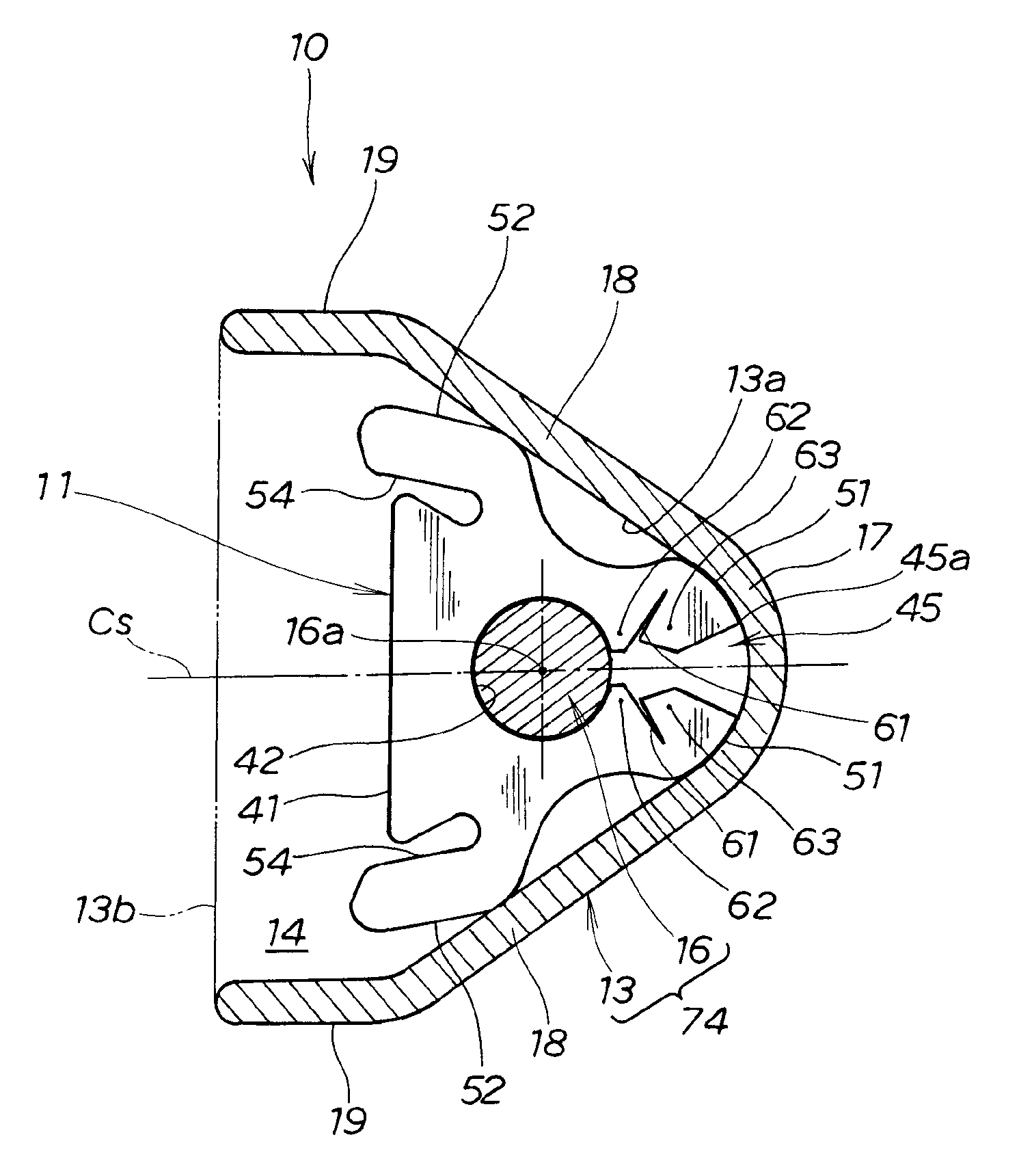
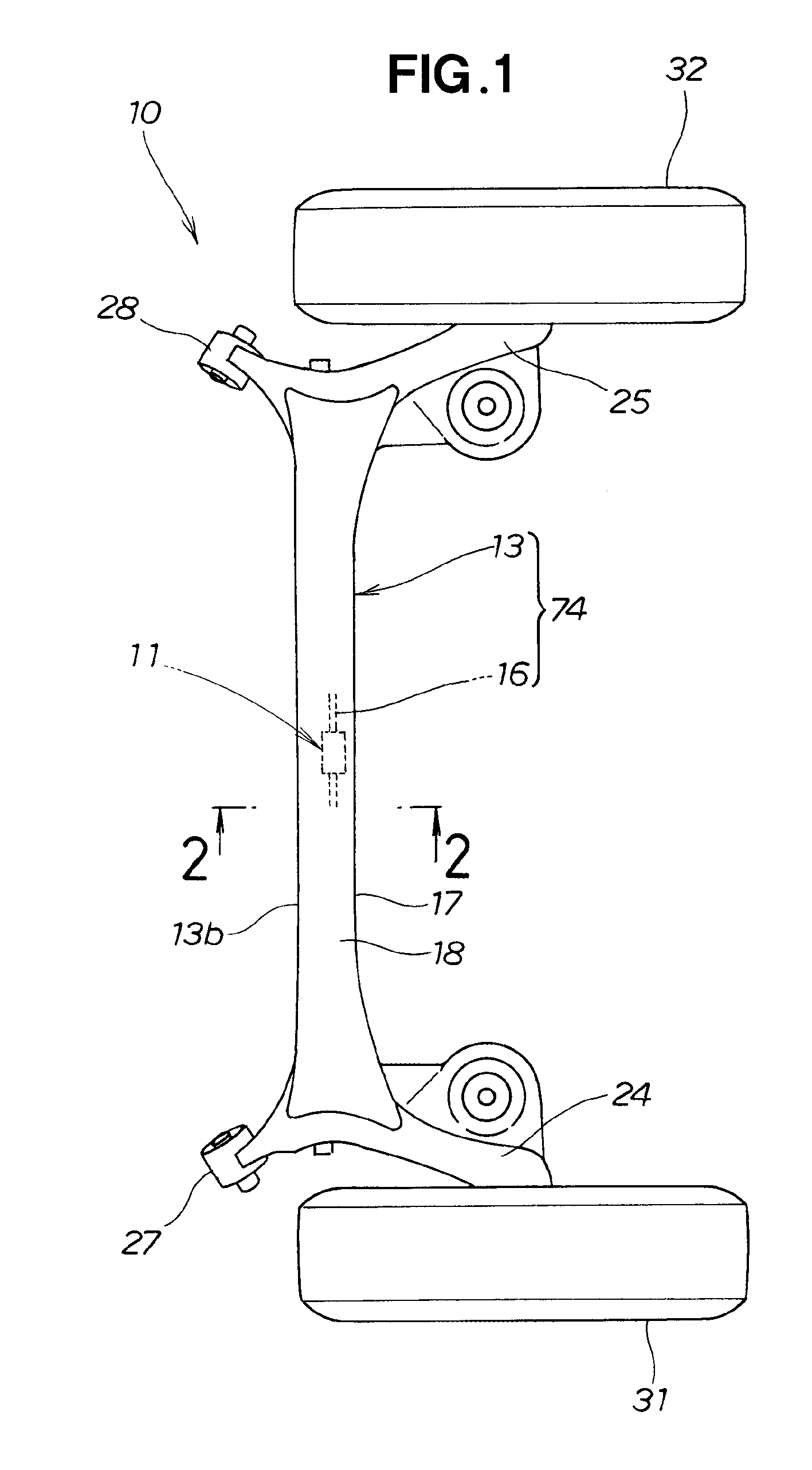
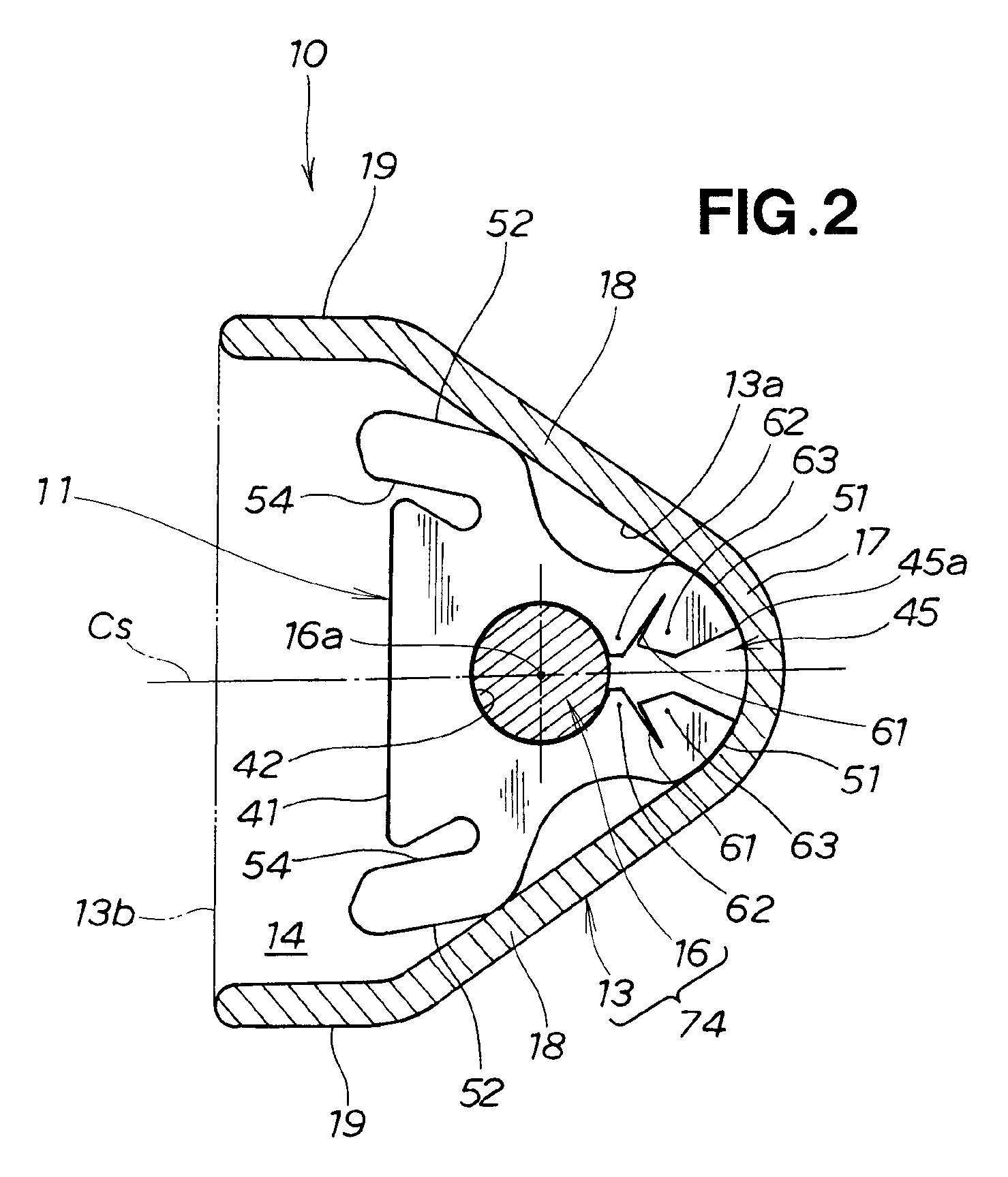
[0035]The following is a description made of a vehicle suspension using the anti-vibration bush in the first embodiment, with reference to FIG. 1 through FIG. 8. As shown in FIG. 1, a vehicle suspension 10 has a bush for isolating a stabilizer from vibration 11, is positioned in the rear portion of the vehicle, and suspends the wheels 31,

[0036]The suspension 10 includes an axle beam 13 (beam component 13) which is long and narrow in the width direction of the vehicle, left and right arms 24, 25 extending to the front and to the rear from both the left and right ends of the axle beam 13, left and right link portions 27, 28 provided on the front ends of the left and right arms 24, 25, and a stabilizer bar 16 bridging both ends of the left and right arms 24, 25. The left and right wheels 31, 32 are rotatably supported at the rear ends of the left and right arms 24, 25.

[0037]This suspension 10 is a so-called axle beam suspension in which the wheels 31, 32 are attached ...

second embodiment

(Second Embodiment)

[0083]The following is a description of a bush for isolating a stabilizer from vibration 11A of a second embodiment, made with reference to FIG. 9. The bush for isolating a stabilizer from vibration 11A of the second embodiment is characterized by the formation of projections and recesses 81 on the pair of second contact surfaces 52, 52. The undulating projections and recesses 81 are arranged at a fixed pitch in the length direction of the bush for isolating a stabilizer from vibration 11A. Because the rest of the configuration is similar to the configuration of the first embodiment shown in FIG. 1 through FIG. 7, further description has been omitted.

third embodiment

(Third Embodiment)

[0084]The following is a description of a bush for isolating a stabilizer from vibration 11B in the third embodiment, made with reference to FIG. 10. The bush for isolating a stabilizer from vibration 11B in the third embodiment is characterized by the formation of a plurality of small projections 82 on the pair of second contact surfaces 52, 52. The plurality of projections 82 can be conical, and are arranged in a staggered pattern on the pair of second contact surfaces 52, 52. Because the rest of the configuration is similar to the configuration of the first embodiment shown in FIG. 1 through FIG. 7, further explanation has been omitted.

[0085]Thus, the bush 11A in the second embodiment and the bush 11B in the third embodiment are characterized by the formation of an irregular surface in at least some (the pair of second contact surfaces 52, 52) of the portion (the pair of first contact surfaces 51, 51 and the pair of second contact surfaces 52, 52) making contact...


PUM

PropertyMeasurementUnit
angleaaaaaaaaaa
inner angleaaaaaaaaaa
forceaaaaaaaaaa

Abstract

A bush for isolating a stabilizer from vibration, is adapted to be fitted from the open end of an axle beam having a substantially U-shaped cross-section, to a stabilizer bar passing through the inside of the axle beam. The bush includes a fitting hole and an opening for guiding the bar into the fitting hole. The opening has a pair of first projections facing each other and a pair of second projections facing each other. When the opening becomes engaged with the bar, the first and second projections sequentially and individually contact with the bar and elastically deform in the direction in which the opening opens. When the fitting hole has engaged with the bar, the bush makes contact with the inner surface of the beam and elastically deforms in the direction in which the opening closes, and this causes the second projections to make contact with the first projections

Description

TECHNICAL FIELD[0001]The present invention relates to a bush adapted to be attached to a stabilizer bar in a vehicle suspension, for isolating a stabilizer from vibration.BACKGROUND ART[0002]In, for example, a rear suspension, there are structures in which the rear wheels are mounted on both ends of an axle beam which is long and narrow in the width direction of the vehicle, and a stabilizer bar bridges both ends of the axle beam. The cross-sectional shape of the axle beam is U-shaped. The stabilizer bar, which is a torsion bar, is arranged inside the axle beam.[0003]While a vehicle is traveling and when the brakes are applied, the axle beam and stabilizer bar are subjected to some vibration. In order to suppress this vibration, an anti-vibration bush is fitted partway along the length of the axle beam. This technology is disclosed in Patent Document 1. Because the anti-vibration bush is fitted onto the stabilizer bar, it is known as a bush for isolating a stabilizer from vibration....

Claims


Application Information

Patent Timeline
Patent Type & Authority Patents(United States)
IPC IPC(8): F16M1/00F16F5/00
CPCF16F1/373B60G21/0551B60G2206/20B60G2204/41B60G2206/73B60G2202/135B60G2204/1222B60G2200/23
Inventor AKAGAWA, TAIJIHASHIMOTO, HARUO
Owner HONDA MOTOR CO LTD
Why Eureka
Try Eureka