Injection nozzle for injecting lubricating oil in engine cylinders and use thereof

Active Publication Date: 2015-09-10
HANS JENSEN LUBRICATORS
View PDF2 Cites 2 Cited by
  • Summary
  • Abstract
  • Description
  • Claims
  • Application Information

AI Technical Summary

Benefits of technology

[0047]This system is possible as the design of the injection nozzles will ensure a more uniform distribution of lubricating oil when a dosing source in the form of a pump unit is coupled to a plurality of injection nozzles. This is due to the fact that the supply pressure in the lubricating oil affects the core area such that the force moving the valve body forward i

Problems solved by technology

By rising pressure in the cylinder there will be a risk that the injection nozzle can leak.
Former injection nozzles are therefore complicated due to the formation of internal ducts.
Moreover, the former injection nozzles are disadvantageous as there may be a blocking of the free movement of the valve body.
This problem is particularly seen in connection with injection nozzles where the valve body moves backwards against the oil flow, though occurring in the prior are injection nozzles as well where the valve body moves forward with the flow of the supplied oil.
The problem with free movement is caused by the fact that the lubricating oil can contain relatively large particles which are e.g. introduced in the lubricating oil in connection with production/storage/transport of the lubricating oil.
In practice when working with valve bodies in the form of needles in needle valves, it can be difficult to filter off p

Method used


Image

  • Injection nozzle for injecting lubricating oil in engine cylinders and use thereof
  • Injection nozzle for injecting lubricating oil in engine cylinders and use thereof
  • Injection nozzle for injecting lubricating oil in engine cylinders and use thereof

Examples


second embodiment

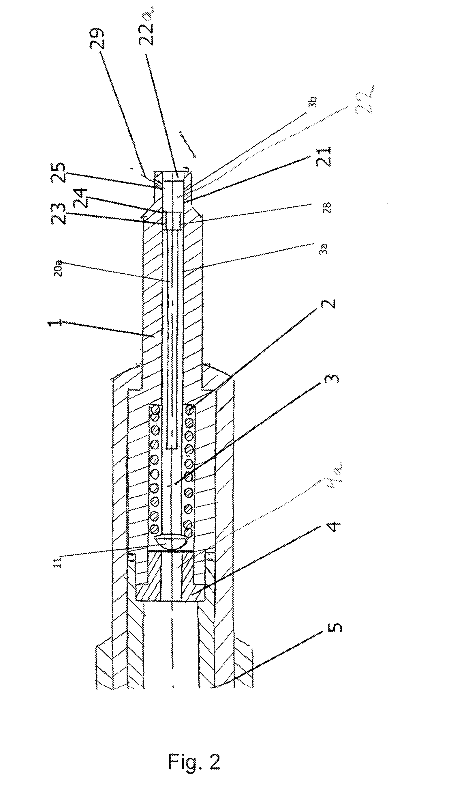
[0110]FIG. 3 is a view corresponding to FIG. 2, though illustrating an injection nozzle 101a. This embodiment differs from the one described above by a different design of the pressurised oil supply ducts 62. The pressurised lubricating oil is supplied to the annular chamber 28 from the pressure chamber 27 around the valve body 67 and the spring 2 via the pressurised oil supply ducts 62 formed as borings in the wall of the nozzle rod. The bevellings 20 in the valve body 3 can hereby be omitted. By this embodiment, the head 11a of the valve body 3 is cylindrical with flat end face for contact against the stop 4 (not shown in FIG. 3).

[0111]The other elements and functions will be as described for the injection nozzle shown in FIGS. 1 and 2.

third embodiment

[0112]FIG. 4 is a view corresponding to FIG. 2, but illustrating an injection nozzle 10 lb. This embodiment differs from the above description by a different design of the pressurised oil supply ducts 66 which are here formed by the nozzle rod 1 in the cylindrical valve seat boring 21 having at least one longitudinal groove 67, which together with the cylindrical sealing face 3a of the valve body form pressurised oil supply ducts 66 connecting the pressure chamber 27 with the annular chamber 28.

fourth embodiment

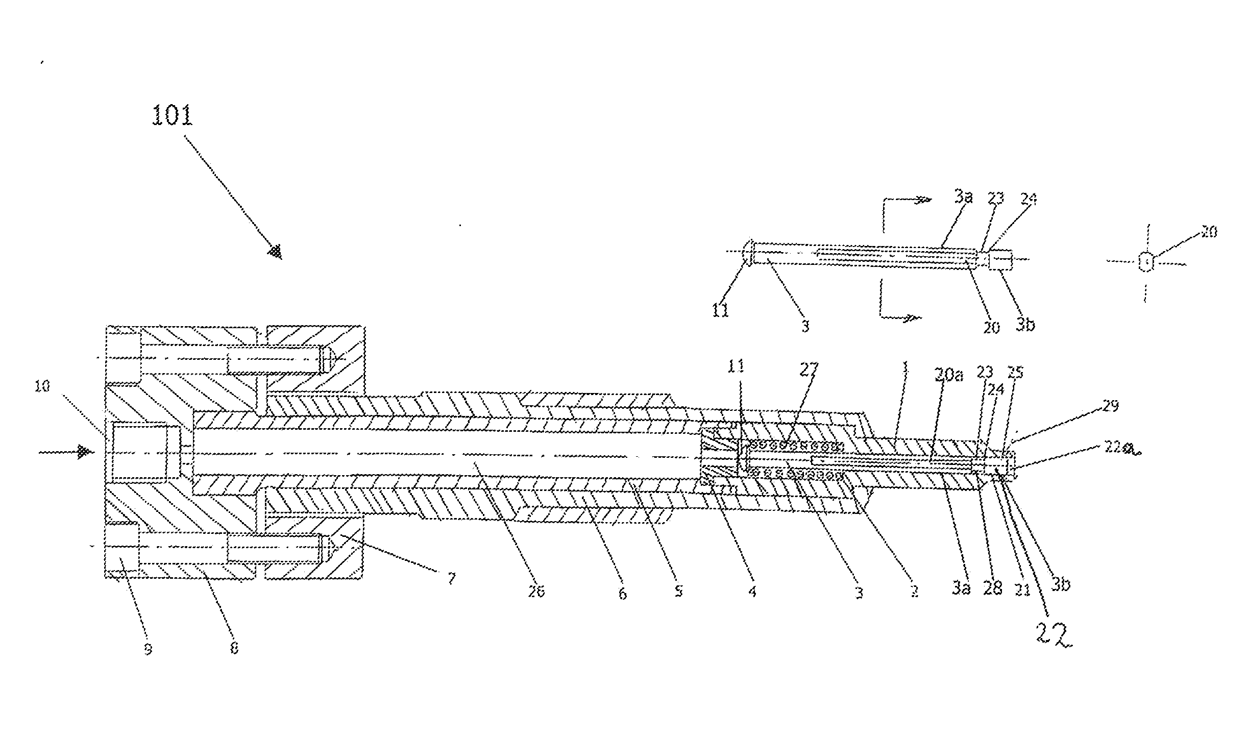
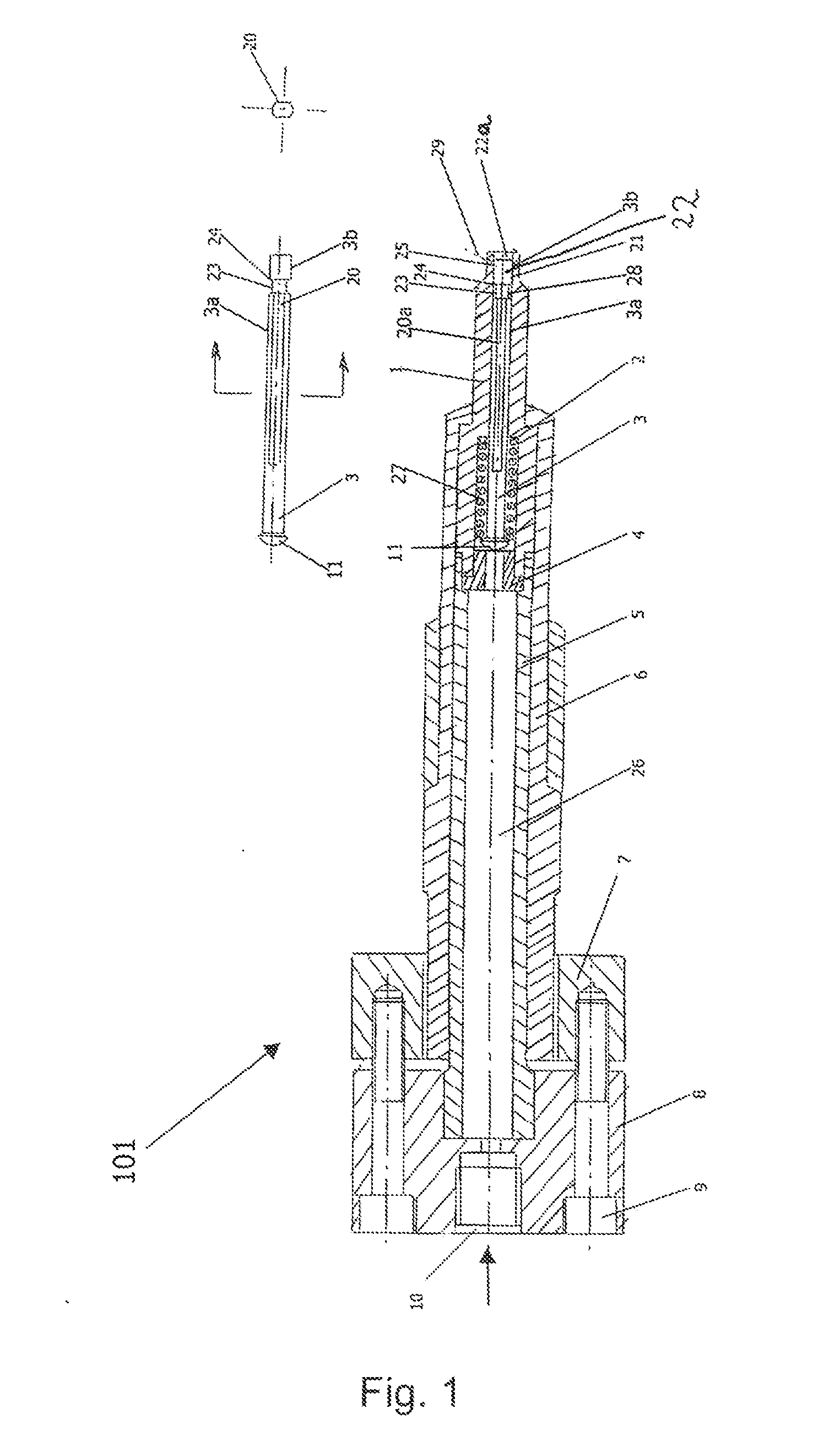
[0113]FIG. 5 shows an injection nozzle 101c. In this embodiment, a dose of pressurised lubricating oil is delivered through the union 10 and on into the duct 26 and the pressure chamber 27. The valve body 3 is pressed in direction towards the nozzle outlet when the force from the oil pressure is large enough to surmount the force from the spring 2. This part of the injection nozzle operates in the same way as the injection nozzle shown in FIGS. 1a and 1b.


PUM


Abstract

An injection nozzle for use in injecting lubricating oil into cylinders in large engines is provided. The nozzle is adapted for fastening in a cylinder wall with a nozzle rod extending through the cylinder wall and with a nozzle outlet at the inner end of the nozzle rod. The nozzle rod includes a cylindrical valve seat boring with a displaceable valve body having a cylindrical sealing face which interacts with the cylindrical valve seat boring of the nozzle rod, the valve body biased by a spring for effective closing of the valve. The valve body is formed by a cylindrical rod having a turned recess in the cylindrical sealing face of the valve body. The turned recess is arranged at the inner end of the valve body with parts of the cylindrical sealing face of the valve body at each side of the turned recess.

Description

CROSS-REFERENCE TO RELATED APPLICATIONS[0001]This application claims priority to PCT Application No. PCT / DK2013 / 050304 having a filing date of Sep. 24, 2013, based off of DK PA 2012 70583 having a filing date of Sep. 25, 2012, the entire contents of which are hereby incorporated by reference.FIELD OF TECHNOLOGY[0002]The following concerns an injection nozzle for use in injecting lubricating oil into cylinders in large engines and adapted with mounting means for fastening in a cylinder wall, with a nozzle rod extending through the cylinder wall and with at least one nozzle outlet at the inner end of the nozzle rod, the nozzle rod including a valve with a cylindrical valve seat boring in which is provided a displaceable valve body having a cylindrical sealing surface which interacts with the cylindrical valve seat boring of the nozzle rod, the valve body having an enlarged head at its outer end with a contact face for a spring disposed around the valve body for establishing a spring-l...

Claims


Application Information

Patent Timeline
IPC IPC(8): F02M61/14F02M59/44
CPCF02M59/44F02M61/14F01M1/08F01M2001/083F16N7/385
Inventor BAK, PEER
Owner HANS JENSEN LUBRICATORS
Why Eureka
Try Eureka