Rolling bearing guide ring

a technology of rolling bearings and guide rings, which is applied in the direction of roller bearings, mechanical equipment, engine components, etc., can solve the problems of increasing the overall weight and moment of inertia of rotating components, affecting the performance of bearings, and increasing the cost of handling and manufacturing, so as to achieve the effect of improving and improving efficiency

Active Publication Date: 2015-09-10
AB SKF
View PDF8 Cites 5 Cited by
  • Summary
  • Abstract
  • Description
  • Claims
  • Application Information

AI Technical Summary

Benefits of technology

[0007]In view of the above-mentioned and other drawbacks of the prior art, a general object of the present invention is to provide an improved and more efficient guide ring for rolling element bearings.

Problems solved by technology

However, for a rolling bearing, or bearing assembly, comprising a guide ring, the added weight from the guide ring increases the overall weight and moment of inertia of the rotating components.
The guide ring also impedes the performance of the bearing and increase the cost for handling and manufacturing.

Method used


Image

  • Rolling bearing guide ring
  • Rolling bearing guide ring
  • Rolling bearing guide ring

Examples


Embodiment Construction

[0040]In the drawings, similar, or equal elements are referred to by equal reference numerals.

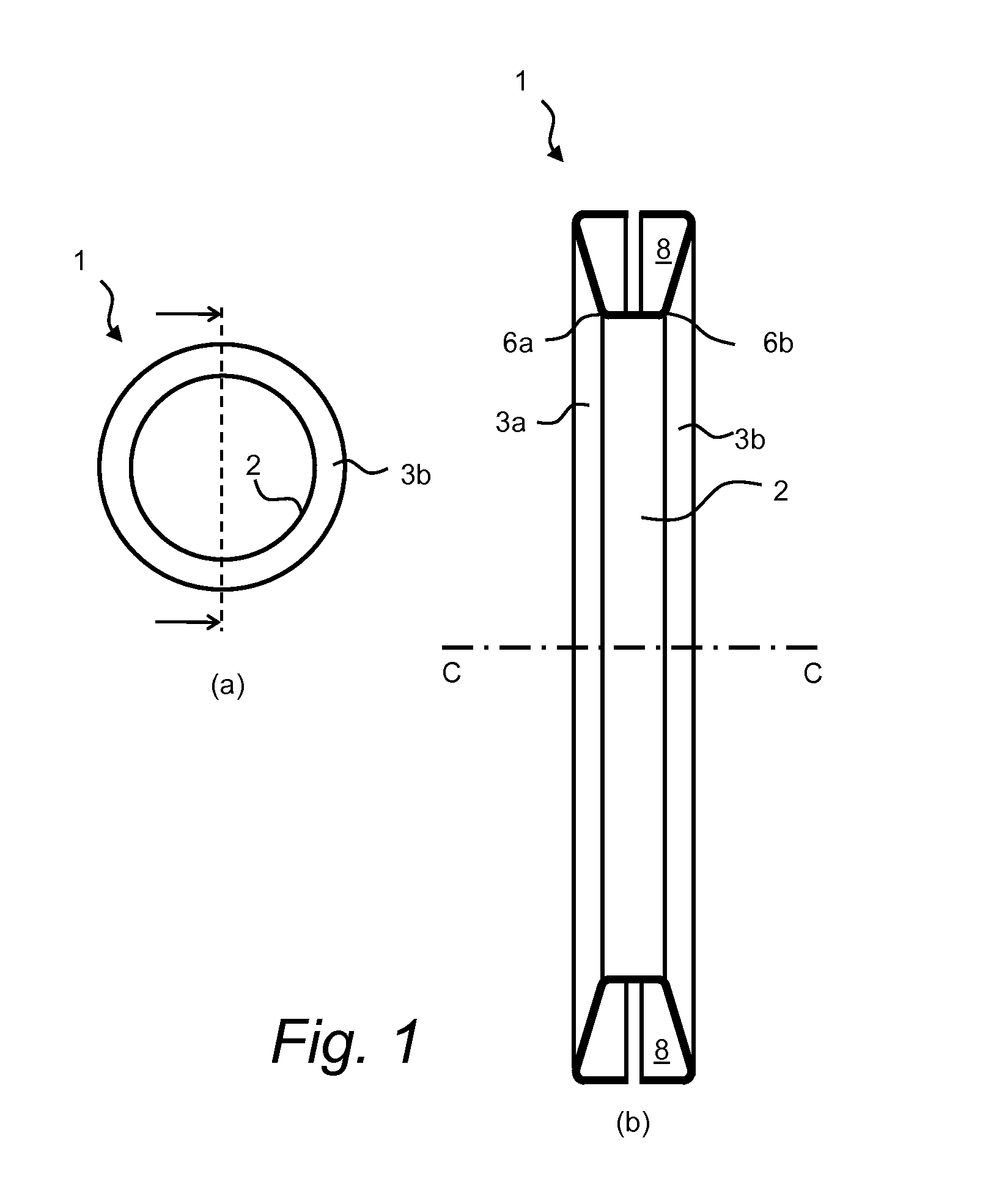
[0041]In FIGS. 1a-b, an embodiment of guide ring 1 according to the present invention is shown. In FIG. 1a, the guide ring 1 is shown from the side and in FIG. 1b an enlarged cross-sectional view of the guide ring 1 is shown, as indicated by the dashed line in FIG. 1a.

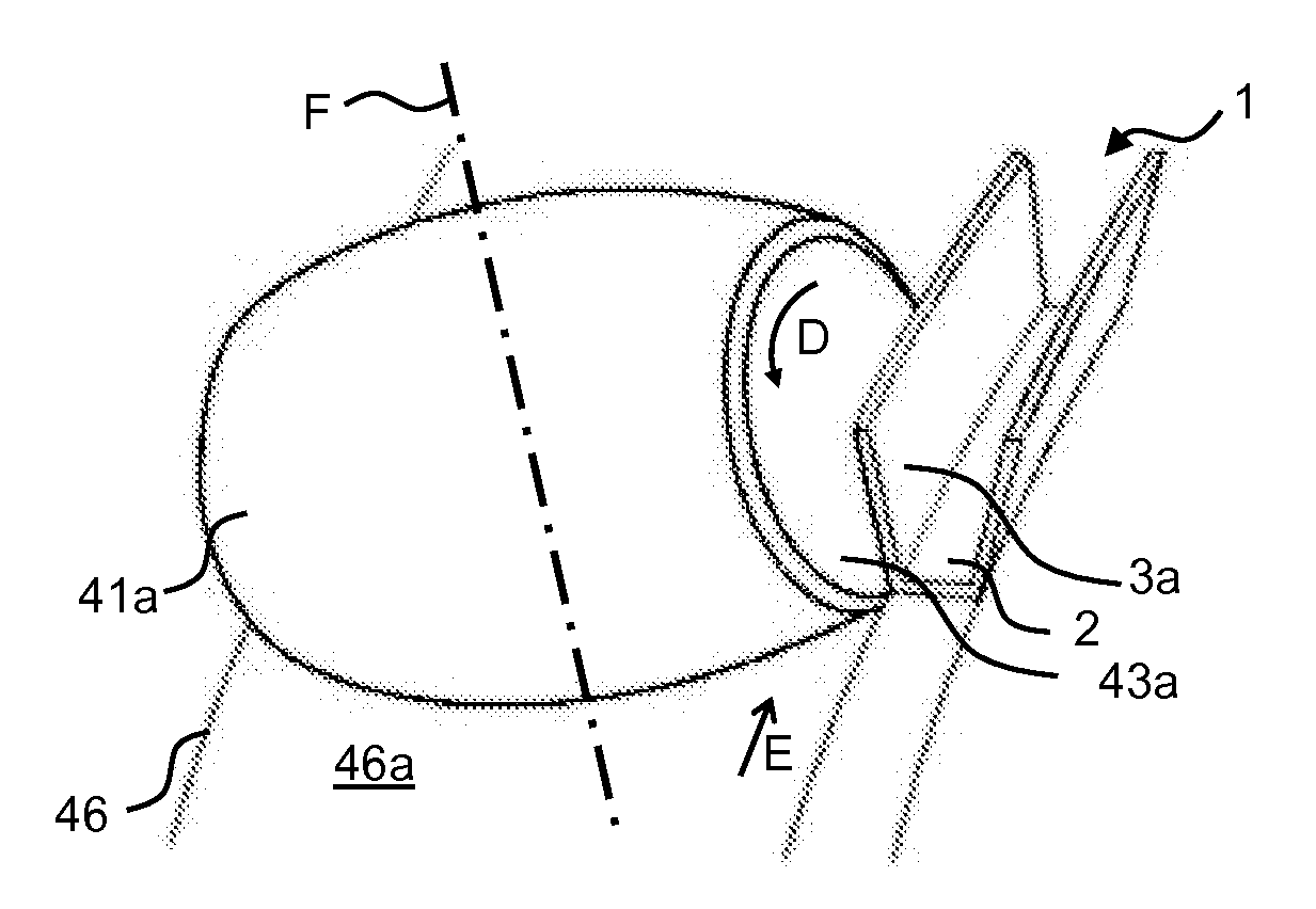
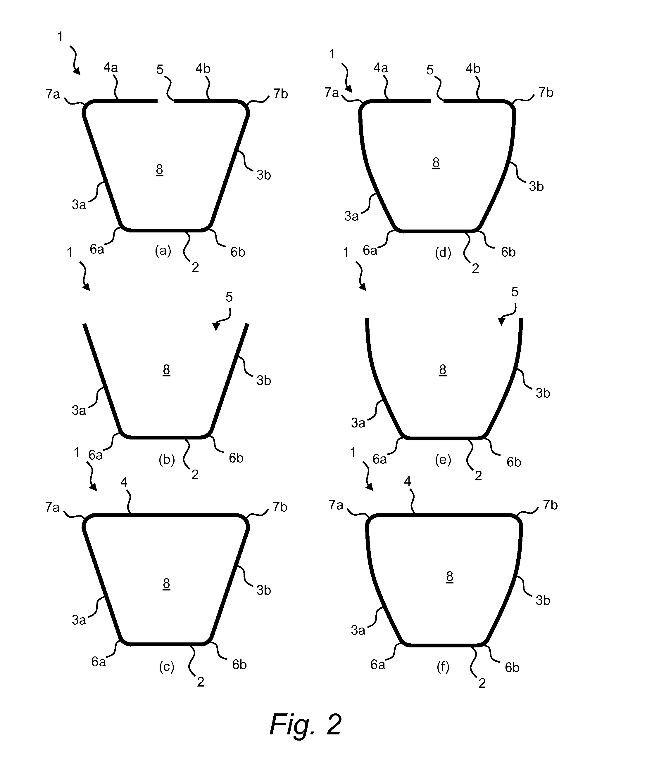
[0042]As illustrated, the guide ring 1 has an annular shape with a centered axial opening along a center axis C. The guide ring 1 further comprises a radially inner base portion 2 which extending annularly around the centered axial opening and which has a cylindrical shape extending axially along the center axis C. The guide ring 1 further comprises a first side portion 3a extending in an outward radial direction from a first axial end portion 6a of the base portion 2, which first axial end portion 6a extends annularly around the centered axial opening in a tilted configuration in relation to the center axis C. The guide ring...


PUM

PropertyMeasurementUnit
thicknessaaaaaaaaaa
thicknessaaaaaaaaaa
thicknessaaaaaaaaaa

Abstract

An annular guide ring for controlling the position of at least one of rolling elements and a bearing cage in relation to an inner ring of a rolling bearing. The guide ring comprises a base portion, a first side portion extending in a radial direction from a first axial end portion of the base portion, and a second side portion extending in a radial direction from a second axial end portion of the base portion, wherein the first side portion and the second side portion are integrally formed with the base portion of a one-piece sheet material. Also described is a method for manufacturing the guide ring for the rolling bearing.

Description

CROSS REFERENCE TO RELATED APPLICATIONS[0001]This is a National Stage Application claiming the benefit of International Application Number PCT / SE2013 / 000146 filed on 20 Sep. 2013 , which claims the benefit of Sweden (SE) Patent Application Serial Number 1200599-7, filed on 4 Oct. 2012, both of which are incorporated herein by reference in their entireties.FIELD OF THE INVENTION[0002]The present invention relates to rolling bearings and rolling bearing components, and more specifically to a guide ring for a rolling bearing. The present invention also relates to a method for manufacturing a guide ring for a rolling bearing.[0003]The guide ring may for example by used for controlling the position of the rolling elements in a rolling bearing, such as a roller bearing, or equivalent, wherein the orientation of rolling elements may be controlled in relation to each other and in relation to the raceways of the rolling bearing. The guide ring may also be used for controlling the position of...

Claims


Application Information

Patent Timeline
Patent Type & Authority Applications(United States)
IPC IPC(8): F16C33/46F16C33/58F16C19/28
CPCF16C33/46F16C33/58F16C19/28F16C19/38F16C23/086F16C33/374F16C33/37F16C33/48F16C33/605Y10T29/49689
Inventor LINDEN, HANSMANNE, NILSJAMES, PETER
Owner AB SKF
Why Eureka
Try Eureka