Device for handling notes of value

a technology for handling devices and notes, applied in the directions of transportation and packaging, atm details, instruments, etc., can solve the problems of slowing down the withdrawal operation, requiring a large amount of installation space for the intermediate storage unit,

Active Publication Date: 2015-09-10
DIEBOLD NIXDORF SYST GMBH
View PDF3 Cites 3 Cited by
  • Summary
  • Abstract
  • Description
  • Claims
  • Application Information

AI Technical Summary

Benefits of technology

[0042]The sliding plate can in particular be moved independent of the belts of the double belt arrangement so that a check of the input and / or output compartment is possible in that the sliding plate is moved thereinto.
[0043]The sliding plate is in particular attached to a third belt, this third belt being drivable by means of a first drive unit and the belts of the double belt arrangement are drivable by means of a second drive unit different from the first drive unit. In this way, the belts and thus the double belt arrangement and the sliding plate can be moved independent of each other at different speeds.

Problems solved by technology

What is problematic with such devices is that much installation space is required for the intermediate storage unit, which space is generally limited in automated teller machines and is thus not available for other components parts.
Further, the intermediate storage of the notes of value slows down the withdrawal operation.

Method used


Image

  • Device for handling notes of value
  • Device for handling notes of value
  • Device for handling notes of value

Examples


first embodiment

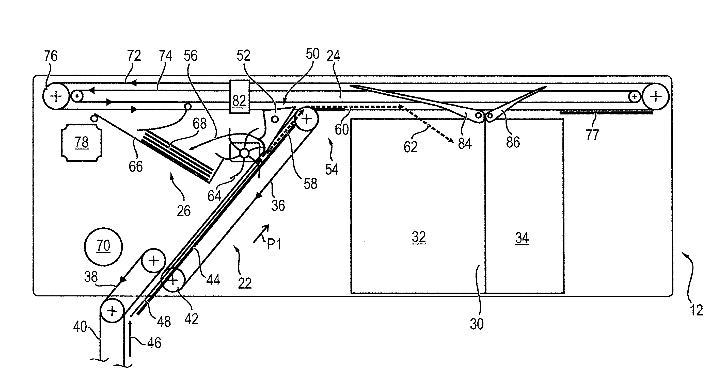
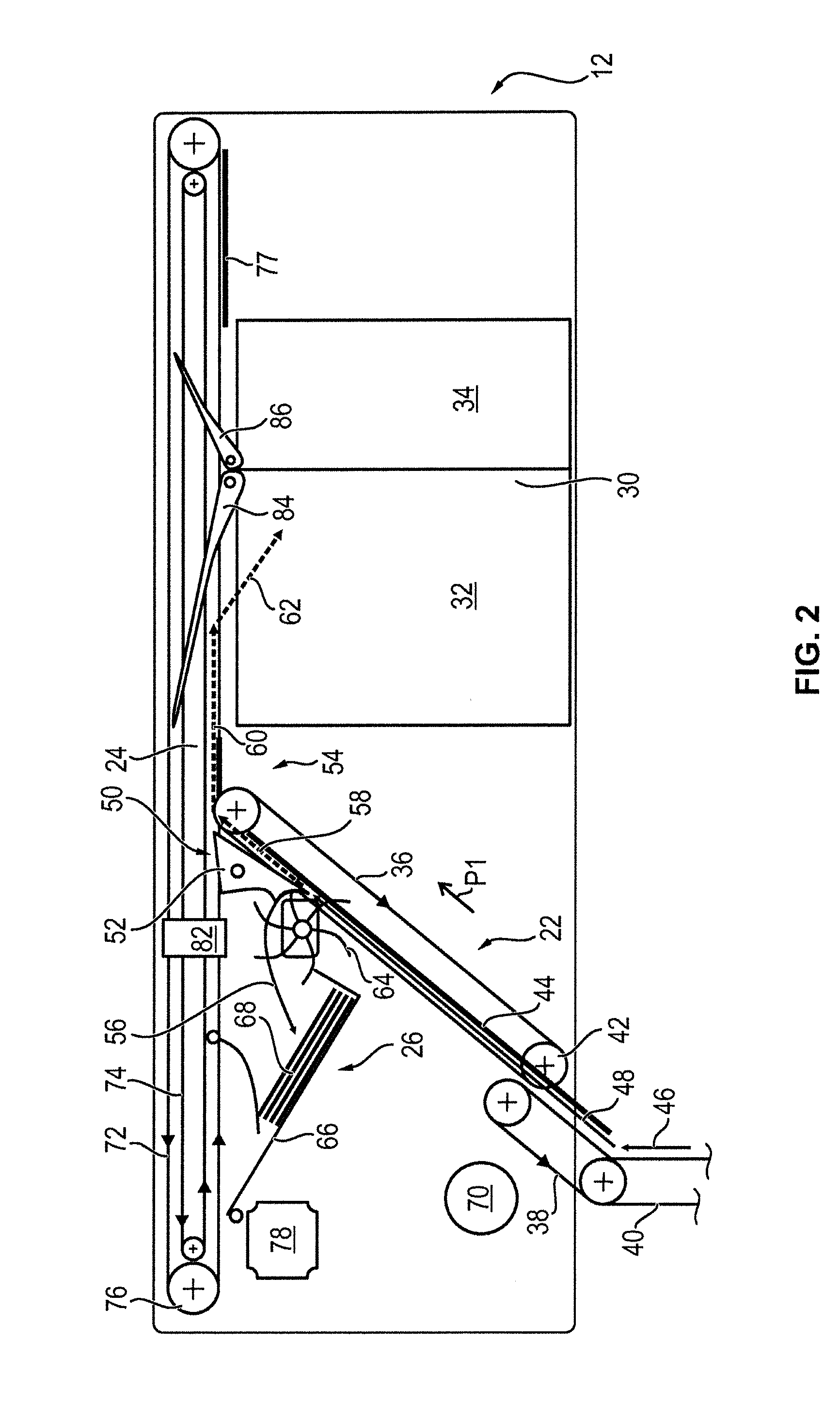
[0063]In FIGS. 2 to 5, each time a schematic illustration of the head module 12 is illustrated, different operating states being shown in the individual Figures. In the following, at first the structure of the head module 12 is explained in more detail before then the individual operating states are described with reference to the respective Figure.

[0064]The first transport unit 22 comprises several drivable belts 36, 38, 40 which are guided over several pulleys, one of which is exemplarily identified with the reference sign. Each time at least one of the pulleys 42 over which a belt 36 to 40 is guided is drivable by means of a drive unit, such as an electric motor, so that the respective belt 36 to 40 is likewise drivable. Further, the first transport unit 22 has several stationarily arranged guiding elements 44 which are in particular designed as guide plates. Here, the notes of value removed from the cash boxes 18 are in particular each transported between the belts 36 to 40 and...

fourth embodiment

[0085]In FIGS. 8 to 10, each time a perspective illustration of the second transport unit 24 is illustrated in different operating states. Elements having the same structure or the same function are identified with the same reference signs.

[0086]The double belt arrangement 100 comprises two parallel running first belts 102 as well as two second belts 104 likewise running in parallel. As a result, it is achieved that the notes of value of the value note wad 68 are guided at two points so that a safe transport of the value note wad 68 is possible.

[0087]At its end regions 132, 134, the sliding plate 120 is movably mounted on two rails 136, 138. The rails 136, 138 at the same time serve as a lateral casing of the second transport unit 24 and in particular serve to protect the value note wad 68 to be transported against unauthorized access.

[0088]At the first end region 132, the sliding plate 120 is attached to a toothed belt 122 which can be driven independent of the belts 102, 104 of t...


PUM


Abstract

A device (10) for handling notes of value has a box receiving area (14) for receiving cash boxes (18) and a first transport unit (22) for transporting of notes of value between the cash boxes (18) and a head module (12). A first switch (50) is provided at a head module side-end of the first transport unit (22). Further, the device (10) has a stacking unit (26), an input and/or output compartment (28) and a reject and retract container (30). In addition, a second transport unit (24) for transporting notes of value between the stacking unit (26), the input and/or output compartment (28) and the reject and retract container (30) is provided. In a first switch position, the first switch (50) guides a note of value removed from the box receiving area (14) to the stacking unit (26) and in a second switch position to the second transport unit (24).

Description

BACKGROUND[0001]1. Field of the Invention[0002]The invention relates to a device for handling notes of value, which comprises a box receptacle for receiving cash boxes and a head module. In the head module, a stacking unit for stacking the notes of value removed from the cash boxes into a wad of value notes, an input and / or output compartment for the input and / or output of notes of value, and a reject and retract container for receiving rejected and non-removed notes of value is provided.[0003]2. Description of the Related Art[0004]In known devices for handling notes of value, such as known automated teller machines, the notes of value removed from the cash boxes are first intermediately stored in an intermediate storage unit until all notes of value determined for the withdrawal have been removed from the cash boxes. The intermediate storage units are often designed in the form of drum storages. The intermediate storage is implemented so that in case multiple pull-offs occur during...

Claims


Application Information

Patent Timeline
Patent Type & Authority Applications(United States)
IPC IPC(8): G07D11/00G07F19/00
CPCG07D11/0021G07F19/202G07D11/0084G07D11/0033G07D7/12G07F19/203B65H2701/1912B65H29/58B65H29/62B65H31/02B65H31/3027B65H31/3063B65H2403/942B65H2404/1114B65H2404/261B65H2404/631B65H2408/13B65H2701/182G07D11/40G07D11/16G07D11/18G07D11/50
Inventor CHOW, KELVIN JOON HORABANOS CUYOS, ROPHIEWIRAWAN, HENGKYPLOTZITZKA, JOERGSEROKA, KARL
Owner DIEBOLD NIXDORF SYST GMBH
Why Eureka
Try Eureka