Piezoelectric element for power generation and power generation device using same

a technology of piezoelectric element and power generation device, which is applied in the direction of generator/motor, mechanical apparatus, machine/engine, etc., can solve the problems of difficult to achieve piezoelectric element commercialization with economic feasibility, low generated voltage, and curved surface of metal thin film not tightly attached to piezoelectric ceramic, etc., to maximize the electromotive force

Active Publication Date: 2015-09-10
BAE SANG CHEOL
View PDF12 Cites 4 Cited by
  • Summary
  • Abstract
  • Description
  • Claims
  • Application Information

AI Technical Summary

Benefits of technology

[0027]As described above, the piezoelectric element for power generation according to the present invention and the power generation device using the same can maximize an electromotive force generated by the piezoelectric element by converting an external force (a natural force, a load force of a person/vehicle or the like) transferred from outside into an instantaneous impact force and transferring the impact force to the piezoelectric element.
[0028]In addition, the piezoelectric element for power generation according to the present invention and the power generation device using the same can further maximize an electromotive force generated by the piezoelectric element by generating an additional impact force using elastic deformation of a metal thin film when an impact force generated by an external force is applied as descri

Problems solved by technology

However, the piezoelectric element for power generation according to the conventional technique has a problem in that since an external force is applied for a relatively long period of time as much as several tens or hundreds of milliseconds, a generated voltage is extremely low due to the characteristic of a piezoelectric material, in which magnitude of an electromotive force generated when an external force of the same magnitude is applied is inverse proportional to the time of applying the external force, and thus it is difficult to accomplish commercialization of the piezoelectric element with economic feasibility.
However, since even the piezoelectric element disclosed in the [Document 2] described below uses a method of fixing a piezoelectric ceramic on a curved deforma

Method used


Image

  • Piezoelectric element for power generation and power generation device using same
  • Piezoelectric element for power generation and power generation device using same
  • Piezoelectric element for power generation and power generation device using same

Examples


first embodiment

Piezoelectric Element for Power Generation

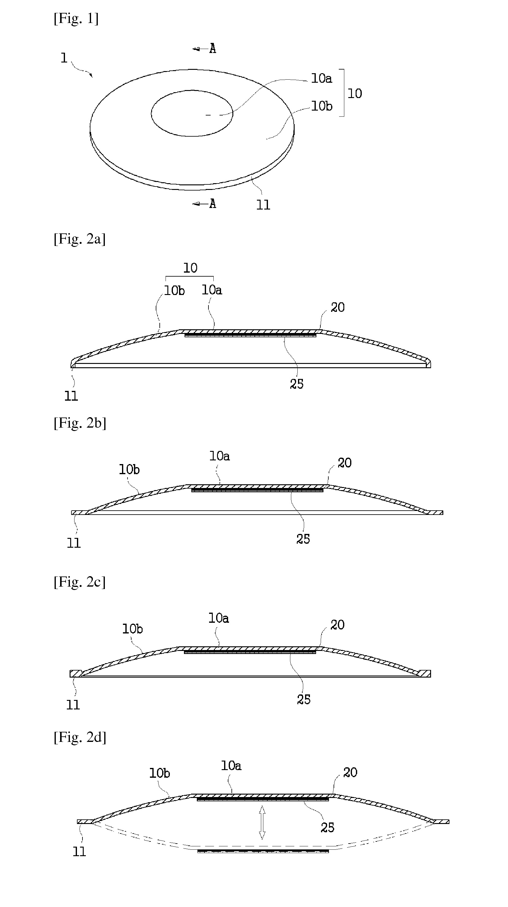
[0047]FIG. 1 is a view showing the configuration of a piezoelectric element for power generation according to a first embodiment of the present invention, and FIGS. 2a to 2c are exploded cross-sectional views taken along the line A-A in FIG. 1.

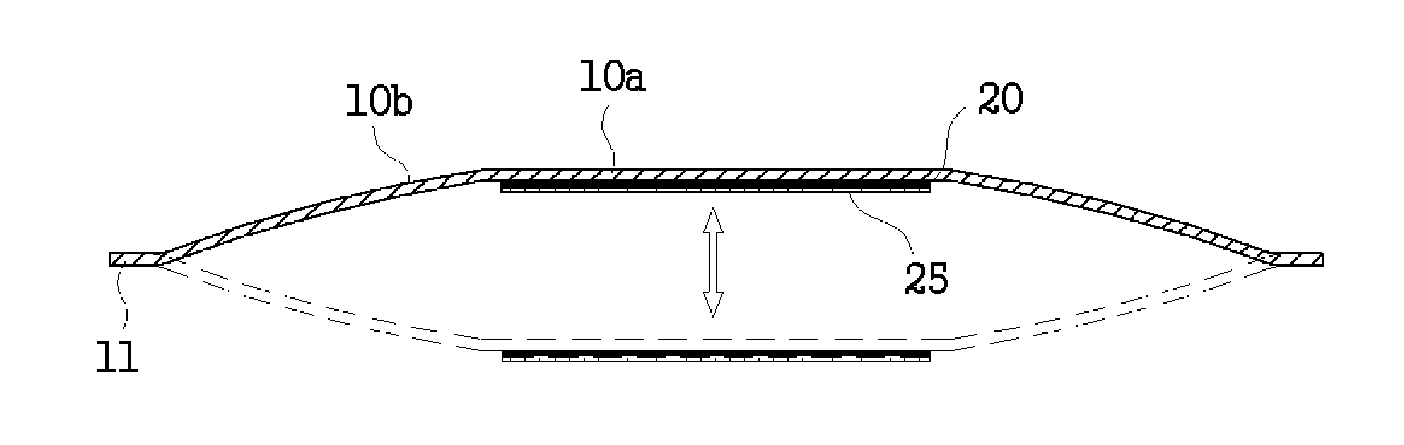
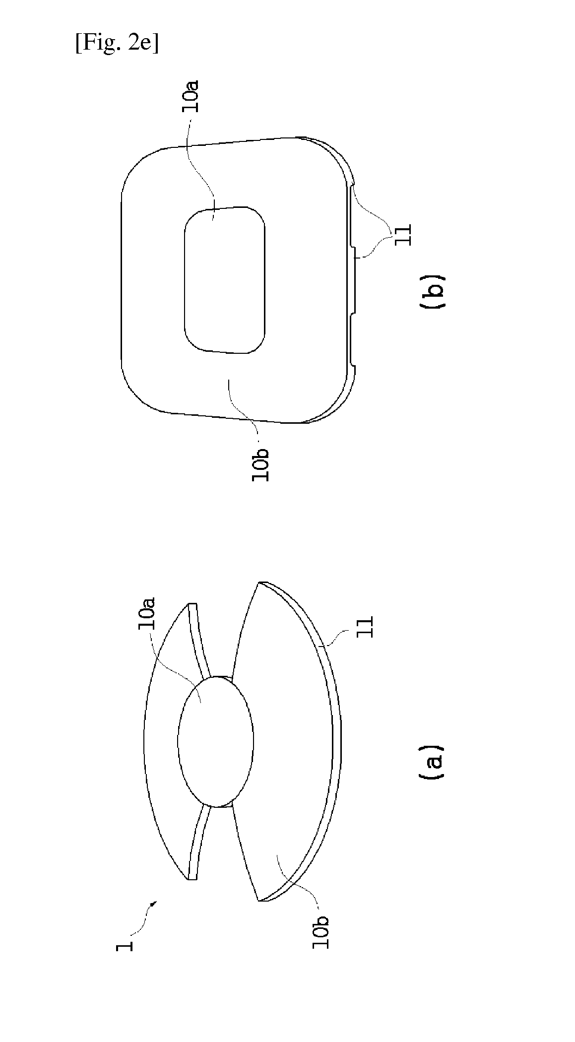
[0048]In addition, FIG. 2d is an exploded cross-sectional view taken along the line A-A to illustrate the operation of the piezoelectric element shown in FIG. 1 when an external force is applied, and FIG. 2e is a view showing another modified example of the piezoelectric element for power generation according to a first embodiment of the present invention.

[0049]A piezoelectric element for power generation according to this embodiment is configured to include a metal thin film 10, a piezoelectric material layer 20 fixed to at least any one of the top surface and the bottom surface of the metal thin film 10, and an electrode layer 25 formed at one side of an outer surface of the piezoelectric material la...

second embodiment

Power Generation Device Using Piezoelectric Element

[0073]FIG. 3 is a view illustrating the configuration of a power generation device using a piezoelectric element according to a second embodiment of the present invention, FIGS. 4 and 5 are exploded cross-sectional views taken along the lines B-B and C-C in FIG. 3, and FIG. 6 is a view showing another modified example of a power generation device using a piezoelectric element according to a second embodiment of the present invention.

[0074]A piezoelectric element used in a power generation device using a piezoelectric element according to this embodiment uses at least any one of the piezoelectric elements 1 for power generation described in the first embodiment, and the same reference numerals are assigned to the configurations the same as those of the first embodiment among the configurations related to the piezoelectric element, and overlapped descriptions will be omitted.

[0075]A power generation device using a piezoelectric elemen...

third embodiment

Power Generation Device Using Kinetic Energy of Train

[0089]FIG. 7 is a perspective view showing the configuration of a power generation device using a piezoelectric element according to a third embodiment of the present invention, FIG. 8 is a plan view showing the configuration of the power generation device shown in FIG. 7, and FIG. 9 is a view illustrating the operation of the external force transfer unit and the stopper unit shown in FIG. 8.

[0090]In addition, FIG. 10 is an exploded view illustrating the detailed configuration of the rotation axis shown in FIG. 9, and FIG. 11 is a view showing the configuration of a piezoelectric power generation unit according to a third embodiment of the present invention.

[0091]A power generation device using a piezoelectric element according to this embodiment is configured to include an external force transfer unit 101 for generating a displacement when an external force is applied, a stopper unit 102 installed at one side of the external forc...


PUM


Abstract

A piezoelectric element for power generation and a power generation device using the same according to the present invention can maximize an electromotive force generated by the piezoelectric element by converting an external force (a natural force or a load force of a person/vehicle or the like) transferred from the outside into an instantaneous impact force and transferring the impact force to the piezoelectric element.

Description

BACKGROUND[0001]The present invention relates to a piezoelectric element for power generation and a power generation device using the same, and more specifically, to a piezoelectric element for power generation and a power generation device using the same, which can maximize an electromotive force generated by the piezoelectric element by converting an external force (a natural force, a load force of a person / vehicle or the like) transferred from outside into an instantaneous impact force and transferring the impact force to the piezoelectric element.[0002]Generally, a piezoelectric element is a device having a property of generating an electromotive force using a potential difference generated by electrical polarization when a mechanical pressure is applied from outside and, contrarily, generating deformation or stress when a voltage is applied, and although the piezoelectric element is used in an oscillator, a speaker or the like in the prior art, a lot of attempts have been made ...

Claims


Application Information

Patent Timeline
IPC IPC(8): H02N2/18F03B13/14F03B7/00
CPCH02N2/183F03B13/14F03B7/00H02N2/18F03B13/184F05B2220/709Y02E10/30H10N30/30
Inventor BAE, SANG-CHEOL
Owner BAE SANG CHEOL
Why Eureka
Try Eureka