Regenerative hydraulic shock-absorber for vehicle suspension

a technology of hydraulic shock absorber and vehicle suspension, which is applied in the direction of shock absorber, electric generator control, machine/engine, etc., can solve the problems of reducing the total efficiency of conversion from kinetic energy to electric energy by a significant amount, difficult to find the space required to arrange the hydraulic motor and the electric generator associated with each shock absorber, and increasing the complexity of the vehicle suspension system. , to achieve the effect of maximizing the electromotive force and limiting the length, and therefore the electrical resistan

Active Publication Date: 2018-08-21
SISTEMI SOSPENSIONI SPA +1
View PDF41 Cites 6 Cited by
  • Summary
  • Abstract
  • Description
  • Claims
  • Application Information

AI Technical Summary

Benefits of technology

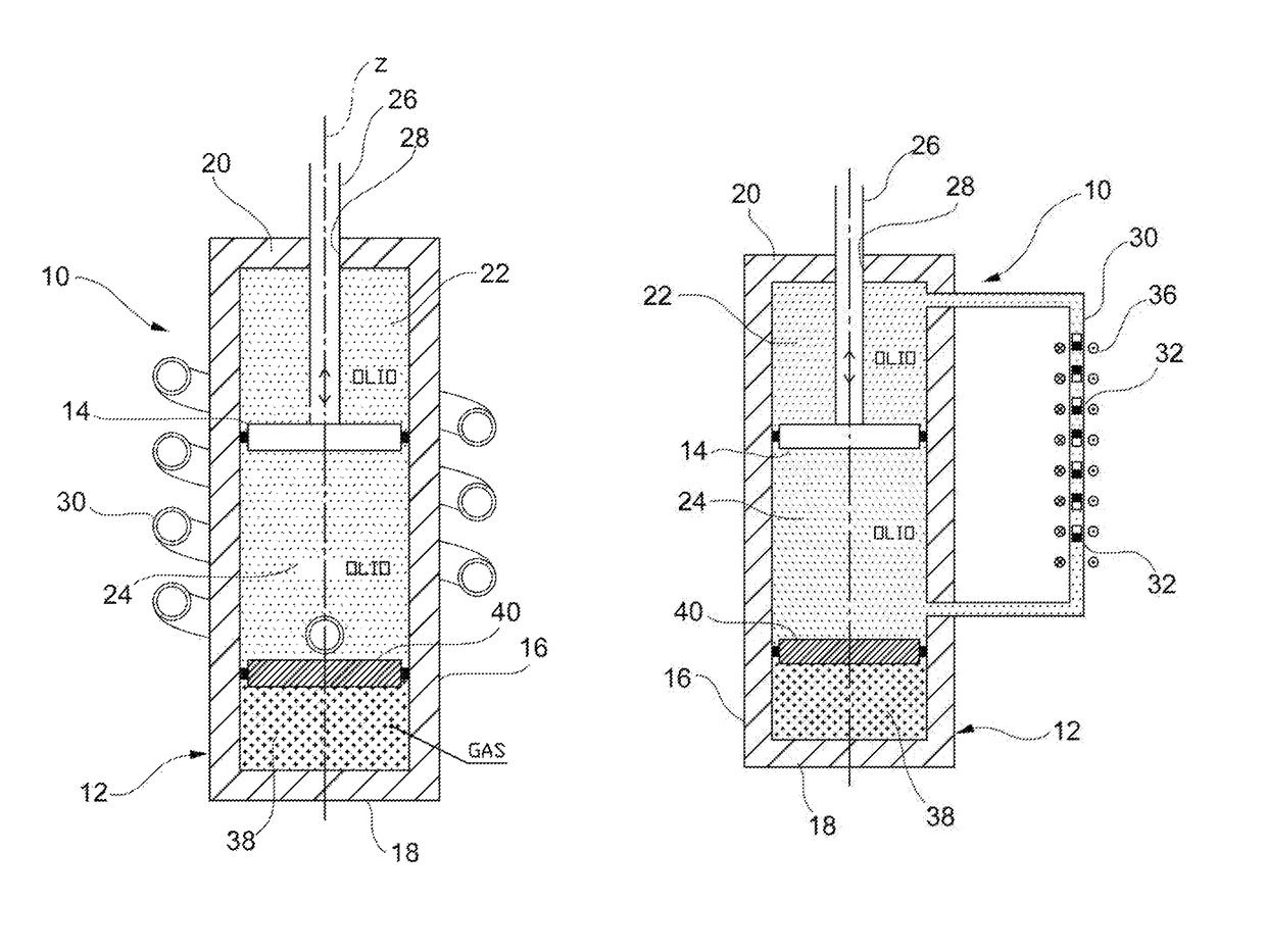
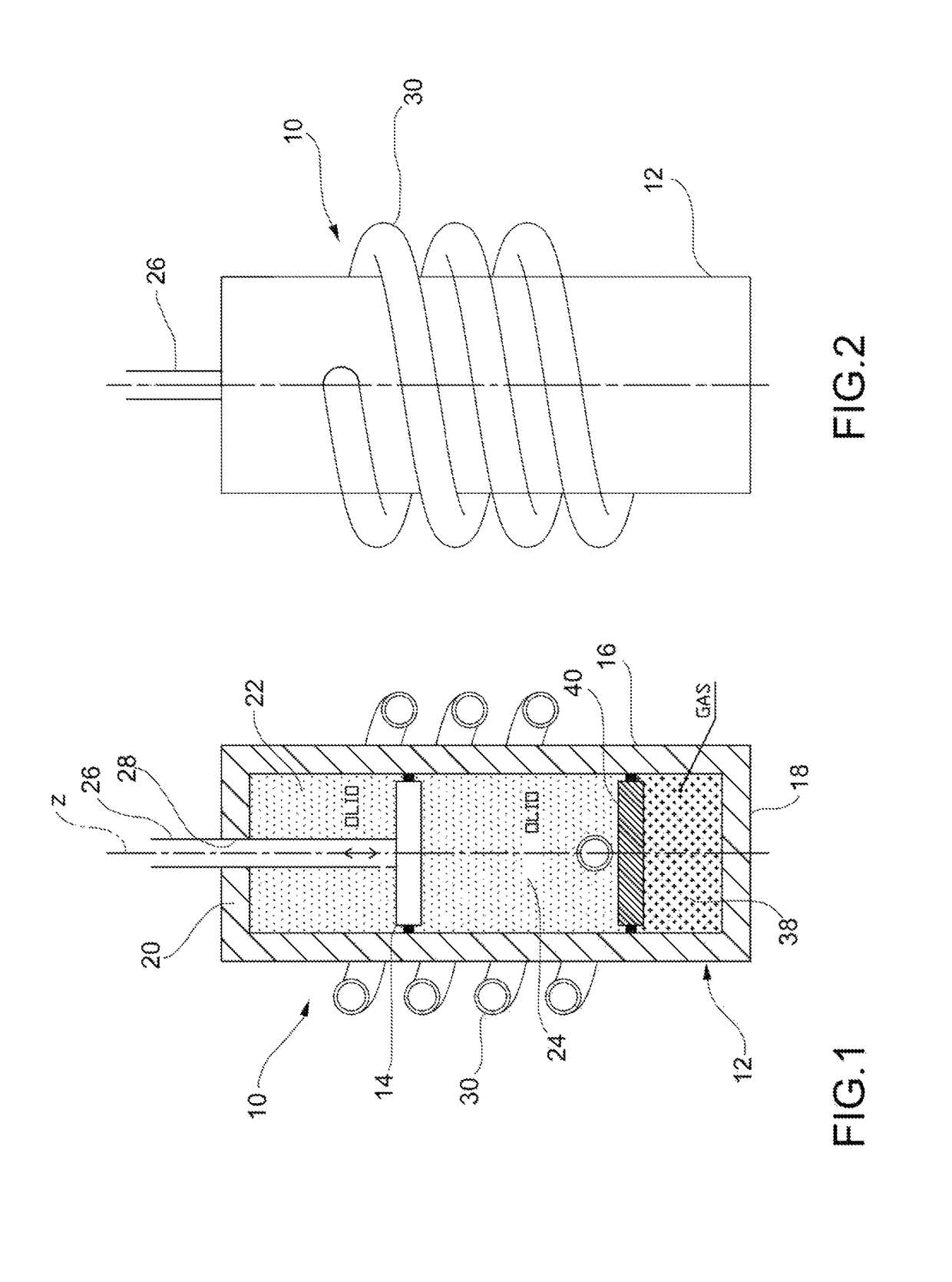
[0018]According to one embodiment, the auxiliary conduit is spirally wound around the cylinder, which makes it possible to obtain an auxiliary conduit of considerably greater length than the stroke of the piston in the cylinder, and therefore to have a large multiplying effect on the speed with which the permanent magnets move in the auxiliary conduit, which results in a high electromotive force generated.
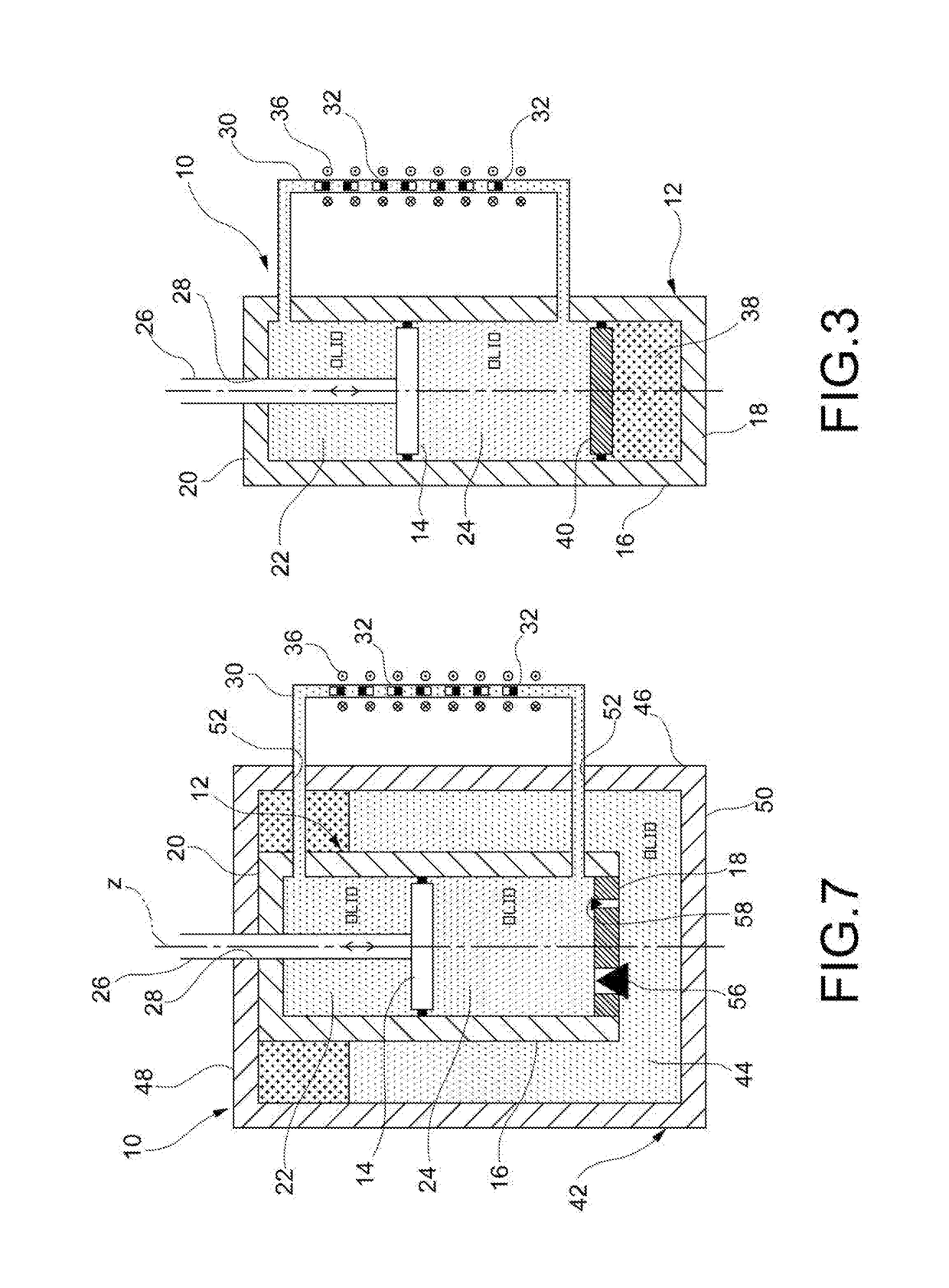
[0020]According to a further aspect of the invention, the electric energy generating device comprise at least one electric winding wound around a portion of the auxiliary conduit, in such a way that the movement of the permanent magnets along the auxiliary conduit alters the magnetic flux concatenated with this / these winding(s), thus generating an induced electromotive force in this / these winding(s), and furthermore the auxiliary conduit is sized in such a way that the ratio of the flow cross-section area of the auxiliary conduit to the internal working cross-section area of the cylinder is equal to a given value less than one, and the ratio of the length of the auxiliary conduit to the length of the piston stroke is greater than the reciprocal of this value. Furthermore, the length of the train of permanent magnets is greater than the length of the portion of auxiliary conduit around which the at least one electrical winding is wound. This makes it possible to maximize the electromotive force generated and, at the same time, the electrical efficiency of the system. On the one hand, it ensures that all the turns of the winding are always affected by the magnetic flux, irrespective of the position of the train of permanent magnets inside the auxiliary conduit, thus maximizing the electromotive force generated. On the other hand, it limits the length, and therefore the electrical resistance, of the winding, thus maximizing the electrical efficiency.

Problems solved by technology

Regenerative shock-absorbers of the type indicated above have first of all the disadvantage that their total efficiency in the conversion from kinetic energy to electric energy is significantly less than 100%, for example of the order of 30%, as a result especially of hydraulic and mechanical losses in the hydraulic motor.
Furthermore, providing for each shock-absorber a hydraulic motor and an electric generator coupled thereto naturally makes the vehicle suspension system more complex, heavier and more expensive.
In addition, it may be difficult to find the space required to arrange the hydraulic motor and the electric generator associated to each shock-absorber.
This known solution has a series of disadvantages which make it practically unusable.
Secondly, since only a small number of turns of the electric windings are affected by the magnetic flux generated by the permanent magnets, the electromotive force generated by the shock-absorber is correspondingly small.
Furthermore, the great length of the electric winding, equal to the length of the portion of auxiliary conduit around which the winding is arranged, entails a reduction in the electrical efficiency of the shock-absorber.

Method used


Image

  • Regenerative hydraulic shock-absorber for vehicle suspension
  • Regenerative hydraulic shock-absorber for vehicle suspension
  • Regenerative hydraulic shock-absorber for vehicle suspension

Examples


Embodiment Construction

[0039]With reference first to FIGS. 1 to 3, a regenerative shock-absorber (hereinafter simply referred to as “shock-absorber”) according to a first embodiment of the present invention is generally indicated 10. The shock-absorber 10 comprises first of all, in a per-se-known manner, a cylinder 12 having a longitudinal axis z (typically oriented vertically or slightly inclined with respect to the vertical) and a piston 14 mounted slidably inside the cylinder 12 along the axis z. The cylinder 12 is filled with a hydraulic working fluid (typically oil, which proves to be an almost incompressible fluid). The cylinder 12 comprises a cylindrical lateral wall 16, a lower wall (or bottom wall) 18 and an upper closure assembly (or cap) 20. The piston 14 splits the internal volume of the cylinder 12 into two variable-volume working chambers, namely an upper working chamber, or extension chamber, 22 and a lower working chamber, or compression chamber, 24. A rod 26 is rigidly connected to the pi...


PUM


Abstract

The shock-absorber comprises: a cylinder containing a hydraulic working fluid; a piston slidably arranged in the cylinder so as to split the cylinder into two variable-volume working chambers, namely a first working chamber, or extension chamber, and a second working chamber, or compression chamber; an auxiliary conduit in fluid communication on one side with the first working chamber and on the other with the second working chamber; a train of permanent magnets slidably arranged in the auxiliary conduit so as to reciprocally move along the auxiliary conduit, dragged by the working fluid flowing between the first and second working chambers through the auxiliary conduit as a result of the reciprocating motion of the piston in the cylinder; and electric energy generating device for generating electric energy by exploiting the movement of the train of permanent magnets along the auxiliary conduit.

Description

CROSS-REFERENCE TO RELATED APPLICATIONS[0001]The present application is a National Phase of International Patent Application No. PCT / IB2015 / 058746, filed on Nov. 12, 2015, which claims priority to and all the benefits of Italian Patent Application No. TO2014A001077, filed on Dec. 19, 2014, both of which are hereby expressly incorporated herein by reference in their entirety.BACKGROUND OF THE INVENTION[0002]1. Field of the Invention[0003]The present invention concerns in general a hydraulic shock-absorber for vehicle suspension, particularly for motor vehicle suspension.[0004]More specifically, the present invention concerns a so-called regenerative hydraulic shock-absorber, i.e. a hydraulic shock-absorber comprising a cylinder, a piston arranged slidably inside the cylinder so as to separate the space inside the cylinder into two variable-volume working chambers, and electric energy generating device for generating electric energy using the flow of a working fluid flowing into, or o...

Claims


Application Information

Patent Timeline
Patent Type & Authority Patents(United States)
IPC IPC(8): F02B63/04F16F9/18H02K35/02H02K7/06H02K49/10H02P9/00B60K25/10F16F9/19B60G13/14H02K7/18F16F9/49
CPCB60G13/14B60K25/10F16F9/185F16F9/19H02K7/06H02K7/1876H02K49/102H02P9/008H02K35/02H02K2207/00B60G2206/41B60G2300/60B60K2025/103F16F9/3207F16F2230/10F16F7/1034
Inventor CONTI, PIERO ANTONIOGRECO, GIORDANONEPOTE, ANDREAINGLESE, FRANCESCOMILAZZO, MARIOSTEFANINI, CESARE
Owner SISTEMI SOSPENSIONI SPA
Why Eureka
Try Eureka