
System and method for providing channel equalization in orthogonal frequency division multiplexing (OFDM) wireless systems

a wireless system and orthogonal frequency division multiplexing technology, applied in the field of wireless communication systems, can solve the problems of infeasibility of static directional antennas, severe spectrum shortage in the conventional cellular band, and devices based on mmw have already hit the market, so as to reduce the pilot density, reduce the effect of pilot density and low snr operation

Active Publication Date: 2015-09-10
NEW YORK UNIV
View PDF1 Cites 6 Cited by
  • Summary
  • Abstract
  • Description
  • Claims
  • Application Information

AI Technical Summary

Benefits of technology

The patent describes a technique called Vulcan that can accurately determine channel estimates even in challenging conditions like rapid channel variations and inaccuracy of receivers. This technique leverages the implied relationship between the real and imaginary components of the channel. The patent shows that Vulcan can improve the success rate of wireless communication and reduce the pilot density required. Overall, the patent presents a simple and accurate solution to address the challenges of millimeter wave wireless networks.

Problems solved by technology

An explosion in the number of wireless broadband users has led to a severe spectrum shortage in the conventional cellular bands.
Devices based on mmW have already hit the market, but are limited by their use of highly directional horn antennas to enable short-range, line-of-sight links, within a controlled and static environment, such as in a data center [see, e.g., Ref. 6].
Since such an environment and conditions are very difficult—if not impossible—to achieve in a practical system implement, there is a need for building mmW orthogonal frequency division multiplexing (OFDM) systems “in the wild,” e.g., where line-of-sight is not always available, SNRs are lower, mobility is enabled, and the use of static directional antennas is infeasible.
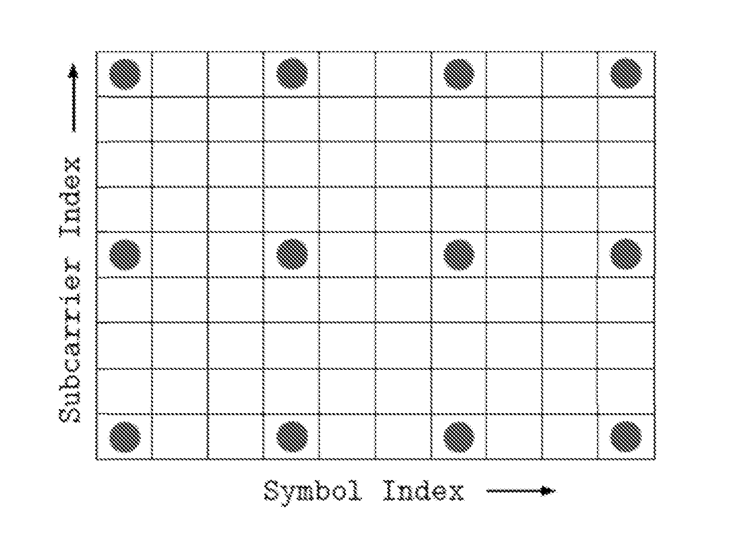
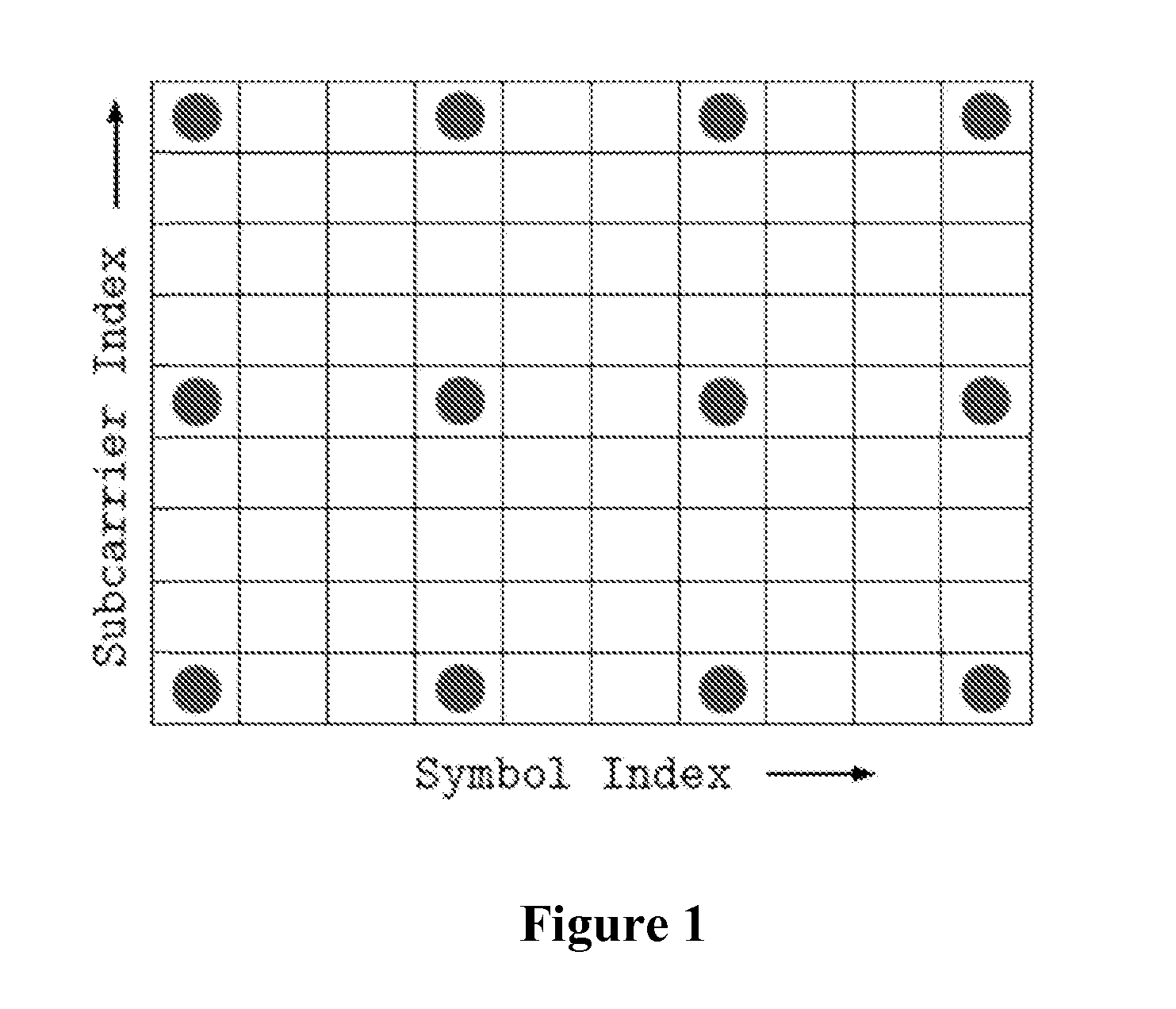
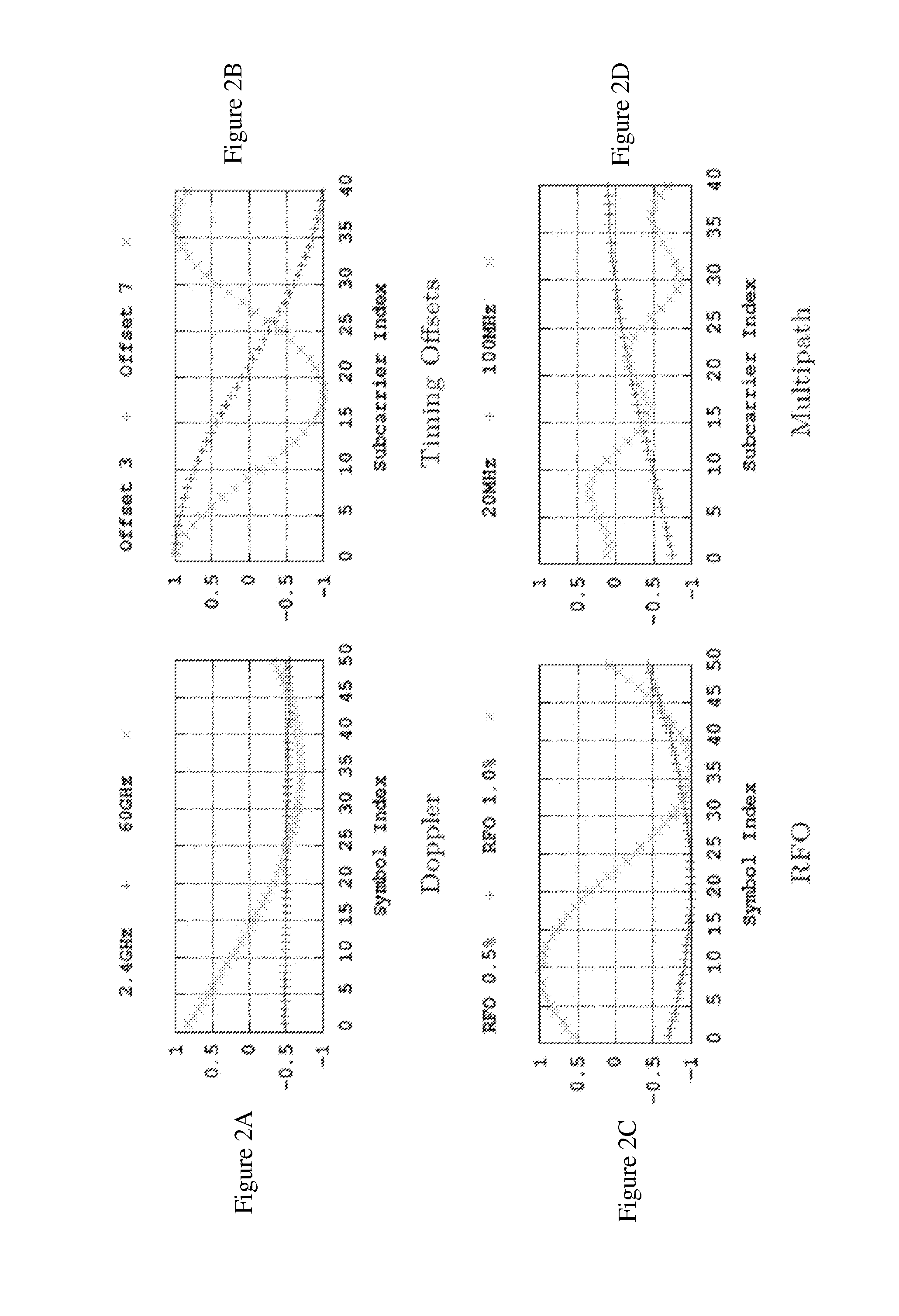
One of the biggest challenges [see, e.g., Ref. 7] in building such mmW OFDM systems is performing accurate channel estimation and equalization because the channel varies rapidly across OFDM subcarriers and / or symbol indices (see FIG. 1).
Existing interpolation mechanisms for interpolating between channel estimates at widely-spaced pilot symbols (9) are not capable of tracking these variations within reasonable bounds of error without requiring prohibitively high pilot densities.
The resulting self-noise becomes very significant, and it cannot be overcome by traditional methods of increasing the SNR such as beamforming or increasing the transmit / receive gains.
Such channel variations may lead to interpolation errors in the real and imaginary components of the channel.
In the case of tightly-spaced modulation constellations such as 64-QAM, even a 10% error in the channel estimate can lead to symbols being incorrectly decoded.
Interpolation errors increase when the underlying channel exhibits more rapid variances, leading to lower quality channel estimates at the receiver.
As mentioned above, existing channel interpolation techniques are generally inadequate to track and compensate for the channel variations described hereinabove.
However, sinusoidal reconstruction is not robust in the presence of multipath interference prevalent in mmW multipath channels, which causes non-sinusoidal variations illustrated in the exemplary FIG. 2(d).
While linear interpolation is popular for its computational efficiency, its main weakness is large interpolation errors when the interpolant between the two pilot locations spans over a crest or trough in the underlying channel component.
Since n is proportional to the OFDM FFT size and the packet size, it can be very large, rendering this technique computationally infeasible for practical mmW systems.
The main weakness of this scheme is large interpolation errors when: a) the pilots used to estimate the channel at an RE span a crest or trough (in 2D space); and b) the channel exhibits variations at different rates across subcarrier and symbol indices.
DDFE works well when channel variations across time are slow, but fails when there is considerable RFO or Doppler.
While Sinc interpolation is optimal in a bandlimited sense, the underlying channel variations are not always bandlimited, leading to interpolation errors.
Another weakness of Sinc interpolation is the Gibbs phenomenon that leads to large interpolation errors at the edges of the packet (FIG. 1).

Method used


Image

  • System and method for providing channel equalization in orthogonal frequency division multiplexing (OFDM) wireless systems
  • System and method for providing channel equalization in orthogonal frequency division multiplexing (OFDM) wireless systems
  • System and method for providing channel equalization in orthogonal frequency division multiplexing (OFDM) wireless systems

Examples


case 1

[0067] d(vert)(i,j)(re)≦d(vert)(i,j)(im): In this exemplary case, a native interpolation can be used to calculate the real component of the channel Re{h(i,j)}. This is because the real component of the channel at that RE is at less of an inflection as compared to the imaginary component. As such, there is a higher level of confidence for performing native interpolation on the real component.

As shown in the exemplary case of the graph of FIG. 3, native interpolation is performed on the real component of the channel between subcarriers −10 and −6.

case 2

[0068] d(vert)(i,j)(im)(vert)(i,j)(re): This case comprises a necessary, although not sufficient, condition to reconstruct the real component from the imaginary and absolute components. If the absolute component happens to be at a high inflection at this location, however, there is less confidence in the reconstruction. Therefore, if d(vert)(i,j)(im)+d(vert)(i,j)(abs)(vert)(i,j)(re), the real component is reconstructed from the imaginary and absolute components. Otherwise, native interpolation is used to determine the real component. Note that if the doubt at a location is undefined, native interpolation is also used. As shown in the exemplary case of the graph of FIG. 3, reconstructed interpolation is performed on the real component of the channel between subcarriers −18 and −14.

[0069]FIG. 10 shows an exemplary flow diagram of an exemplary method estimating, in a single dimension, a frequency response of a communication channel represented by a plurality of sub-carriers according t...


PUM


Abstract

The present disclosure relates to a computer-implemented method for estimating a communication channel response, comprising procedures such as: receiving, via the channel, a signal comprising a plurality of symbols, each comprising a plurality of sub-carriers; determining a pilot sub-carrier response and a pilot sub-carrier metric for one or more pilot sub-carriers; and for one or more non-pilot sub-carriers: i) determining a non-pilot sub-carrier metric; ii) if the non-pilot sub-carrier metric satisfies a criterion, determining a particular component (e.g., real or imaginary) of a non-pilot sub-carrier response as a function of different components of one or more pilot sub-carrier responses; and iii) if the non-pilot sub-carrier metric does not satisfy the criterion, determine the particular component of the non-pilot sub-carrier response as a function of the particular component of one or more pilot sub-carrier responses. Other embodiments include a communication apparatus and a computer-readable medium configurable to perform such procedures.

Description

CROSS-REFERENCE TO RELATED APPLICATION(S)[0001]This application is based upon and claims the benefit of priority from U.S. Patent Application Ser. No. 61 / 950,586, both filed Mar. 10, 2014, the entire disclosure of which is incorporated herein by reference.FIELD OF THE DISCLOSURE[0002]The present application relates to generally to the field of wireless communication systems, and more specifically to improving the performance of orthogonal frequency division multiplexing (OFDM) receivers that estimate the response of a wireless channel based on pilot sub-carriers interspersed with data or other non-pilot sub-carriers.BACKGROUND INFORMATION[0003]An explosion in the number of wireless broadband users has led to a severe spectrum shortage in the conventional cellular bands. The demand for cellular data services is expected to grow at a staggering rate, necessitating orders of magnitude increases in wireless capacity [see, e.g., Refs. 1, 2]. Millimeter wave (mmW) frequencies at 28, 38, a...

Claims


Application Information

Patent Timeline
Patent Type & Authority Applications(United States)
IPC IPC(8): H04L27/26H04L25/02
CPCH04L25/0202H04L27/2649H04L5/0048H04L25/022H04L27/2647H04L25/0232H04L25/0234H04L25/0204H04L25/023
Inventor DHANANJAY, ADITYALI, JINYANGRANGAN, SUNDEEP
Owner NEW YORK UNIV
Learn More