Eureka AIR delivers breakthrough ideas for toughest innovation challenges, trusted by R&D personnel around the world.

RFID reader device and antenna device

Inactive Publication Date: 2015-09-17
CHECKPOINT SYST INC
View PDF4 Cites 4 Cited by
  • Summary
  • Abstract
  • Description
  • Claims
  • Application Information

AI Technical Summary

Benefits of technology

The patent describes a RFID device that can be easily installed at points of sale and adjusted to the environmental conditions. The antenna is designed to concentrate its field in a specific volume, reducing interference with nearby RFID transponders and avoiding false positive reads. The device also has a high magnetic proportion at close range and a symmetrical operation that cancels out E fields at long range, resulting in a desired power drop. This prevents RFID transponders at greater distance from being activated.

Problems solved by technology

The radiation emitted into their surroundings can cause undesired directionality and losses.
Radiating feed lines can also induce interference of broadcast radio and television reception.
This side effect is typically more unpleasant than the slight radiation loss.
They would cancel out if both conductors were spatially coincident, which cannot be practically implemented, however.

Method used


Image

  • RFID reader device and antenna device
  • RFID reader device and antenna device
  • RFID reader device and antenna device

Examples


Embodiment Construction

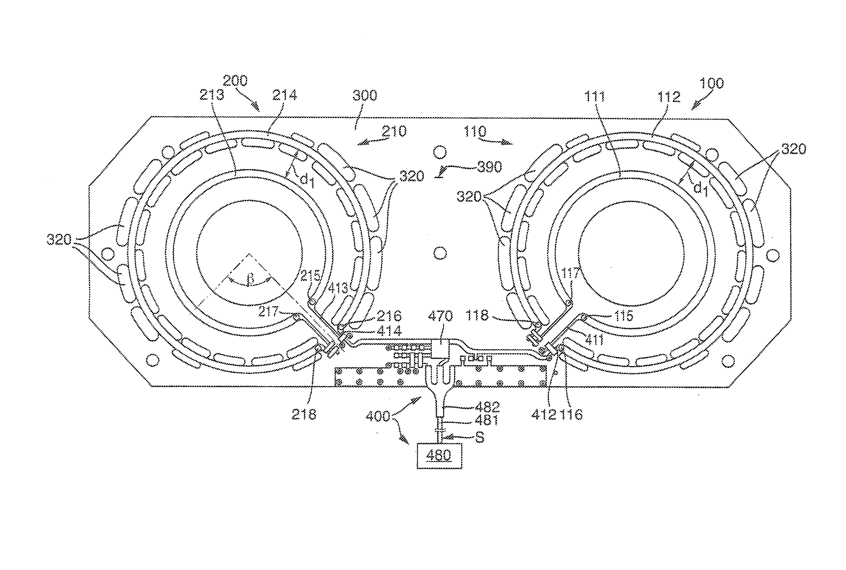
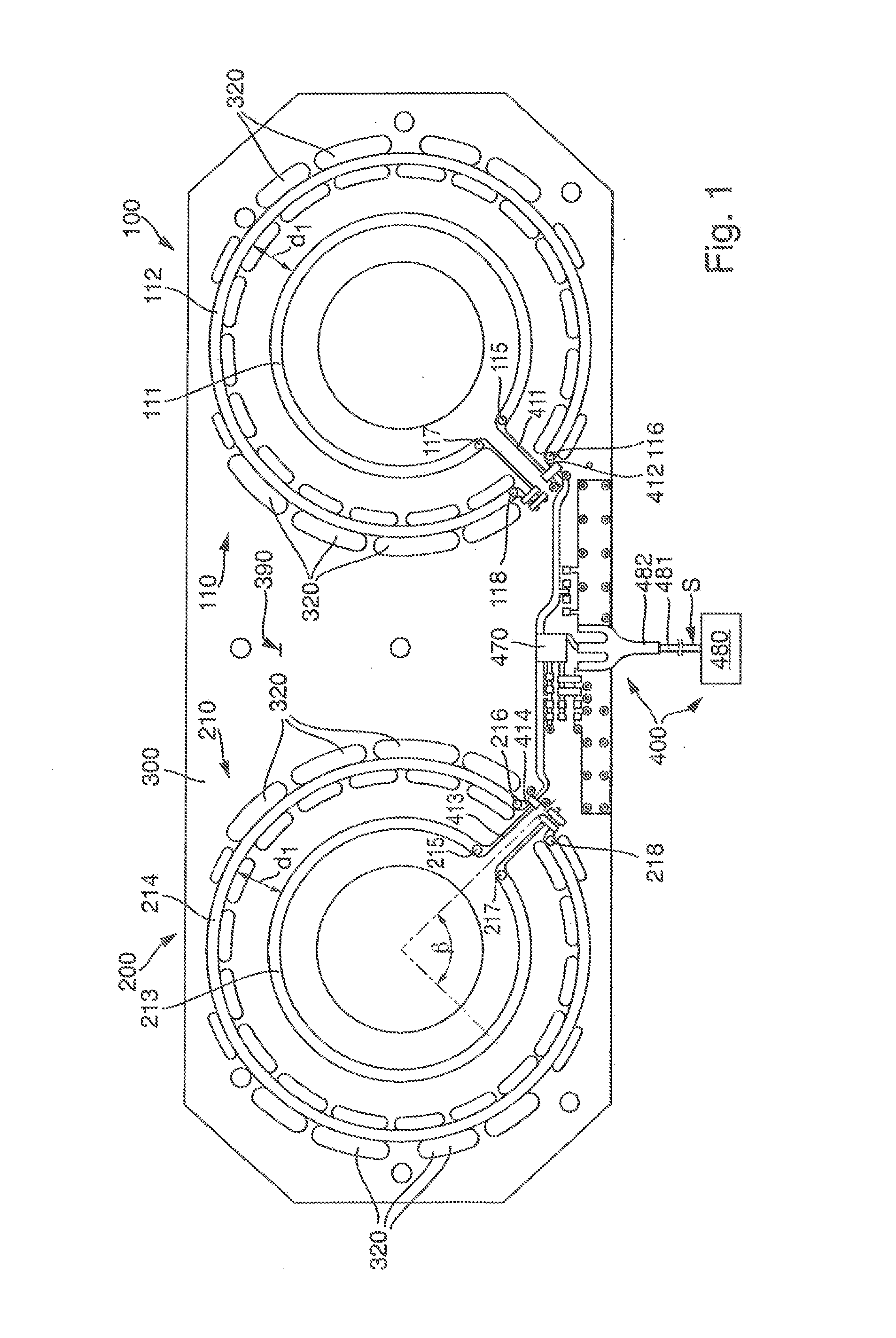
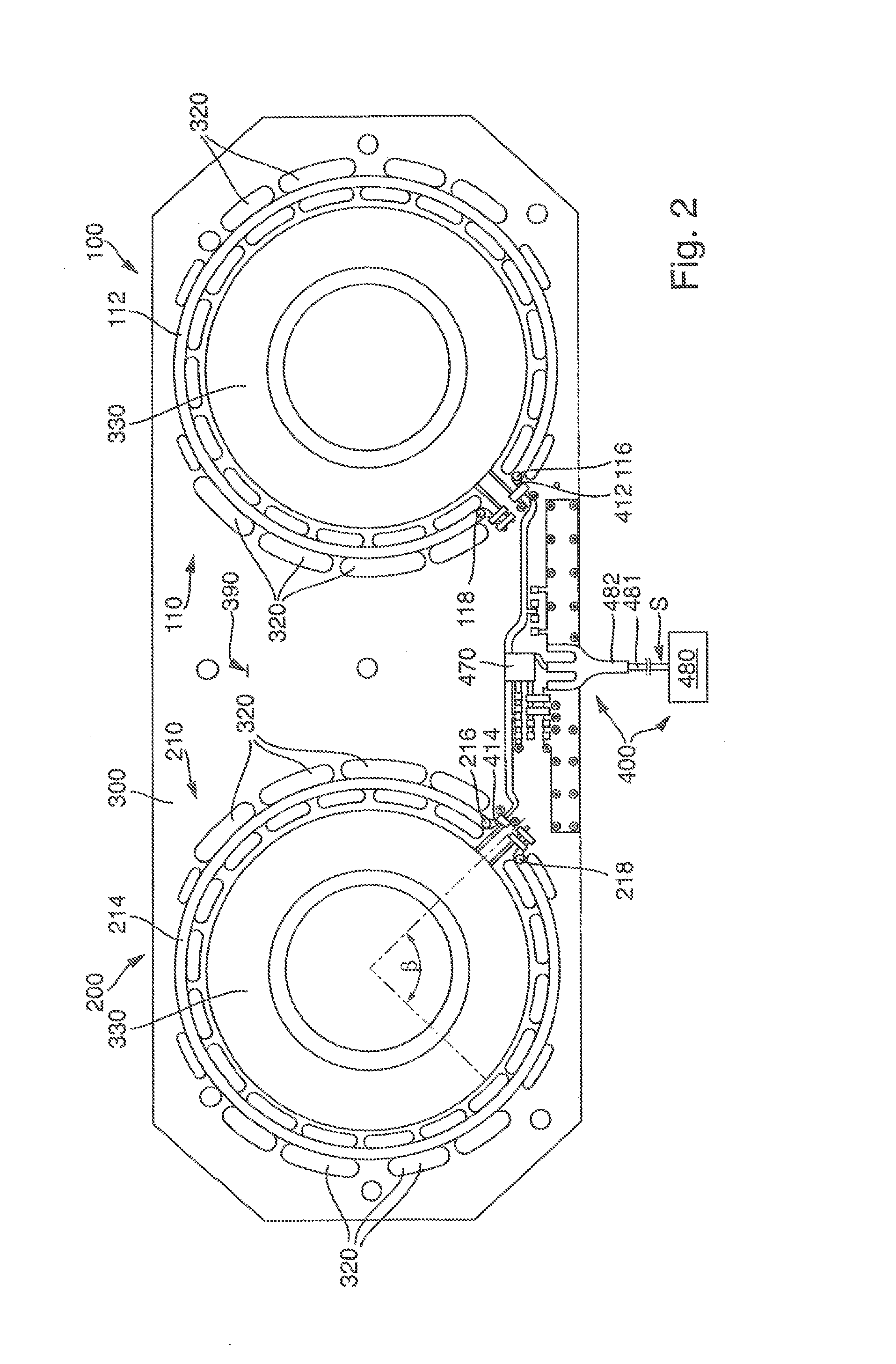
[0031]A first embodiment of an RFID reader device is shown schematically in FIG. 1. The RFID reader device has a circuit 400, which is partially shown as a block 480 and is partially shown as the equipment and conductor track arrangement on the circuit carrier 300. In an embodiment, the RFID reader device is configured to transmit a query signal to an RFID transponder and to receive a response signal based on the query signal. For this purpose, the circuit block 480 of the circuit 400 generates a signal S, which is transmitted via a cable 481, for example, a coaxial cable, to the HF connecting element 482.

[0032]By means of a power splitter of the circuit 400, the power of the signal S is allocated to a first antenna 100 and a second antenna 200. Alternatively to the embodiment of FIG. 1, a plurality of antennas (more than two) can be provided, which are connected to outputs of power splitters. The first antenna 100 may be implemented as a near-field antenna. The first antenna 100 ha...


PUM


Abstract

An RFID reader device and an antenna device have a first antenna implemented as a near-field antenna, wherein the first antenna has a first dual strip line. The first antenna has a first strip line and a second strip line. The first strip line and the second strip line may be implemented in the form of open loops. The first strip line may be implemented inside the open loop of the second strip line.

Description

CROSS-REFERENCE TO RELATED APPLICATIONS[0001]This application claims the benefit of German Patent Application No. 102014003409.7 filed Mar. 13, 2014, the entire contents of which are incorporated herein by reference.BACKGROUND OF THE INVENTION[0002]1. Technical Field[0003]The present invention relates to an RFID reader device and an antenna device.[0004]2. Background Information[0005]Antennas are known from “Rothammels Antennenbuch [Antenna Book]”, A. Krischke, 12th edition, 2001. Various forms of antennas are explained on pages 65 to 71. The antenna has the task of converting the conducting wave originating from the transmitter into the sky wave or vice versa, receiving the sky wave from space and converting it into the conducting wave, which is then fed to the receiver. The antenna is a transmission region, which can be conceived as a spread out line. It acts as an adaptation transformer between line and free space. A progressive wave forms in the case of power adaptation, which i...

Claims


Application Information

Patent Timeline
IPC IPC(8): G06K7/10H01Q7/00H01Q1/22
CPCG06K7/10336H01Q7/00H01Q1/2216G06K7/10356H01Q3/26H01Q21/00
Inventor RAMSCH, GEORG
Owner CHECKPOINT SYST INC
Why Eureka
Eureka Blog
Learn More