Transmitter

Inactive Publication Date: 2015-09-17
NEC CORP
View PDF8 Cites 4 Cited by
  • Summary
  • Abstract
  • Description
  • Claims
  • Application Information

AI Technical Summary

Benefits of technology

[0017]It is therefore an object of the present invention to provide a transmitter in

Problems solved by technology

In particular, the requirement is that amplifiers transmit power with high efficiency because transmission power amplifiers that are placed at the final stage of the transmitter consume a large amount of power.
However, since the

Method used


Image

  • Transmitter
  • Transmitter
  • Transmitter

Examples


Example

The First Exemplary Embodiment

[0035]FIG. 3 is a block diagram showing one configurational example of a transmitter of the first exemplary embodiment.

[0036]The transmitter shown in FIG. 3 includes digital baseband circuit (Digital baseband) 10, two digital transmitters 201 and 202, combiner 30 and control unit 40.

[0037]Digital baseband circuit 10 modulates two signals orthogonal to each other in accordance with the transmit information as the signals to be transmitted, to produce and output two baseband signals (I-signal and Q-signal). The I-signal and Q-signal generated by digital baseband circuit 10 are input to digital transmitters 201 and 202. That is, digital transmitters 201 and 202 are supplied with the same I-signal and Q-signal.

[0038]Digital transmitters 201 and 202 each include changeover switches 211 and 212, RF signal generator 22 and class-D amplifier 23.

[0039]RF signal generator 22 included in digital transmitters 201 and 202 shown in FIG. 3 is equivalent to one in whic...

Example

The Second Exemplary Embodiment

[0104]FIG. 10 is a block diagram showing one configurational example of a transmitter of the second exemplary embodiment.

[0105]The transmitter of the second exemplary embodiment includes N (N is an integer equal to or greater than 2) digital transmitters and is configured to combine the output signals from the individual digital transmitters through N-combiner 80 to output the combined result to the load.

[0106]The transmitter shown in FIG. 10 corresponds to the configuration shown in FIG. 3 in which the number of digital transmitters 20 is further increased. The configuration of each of digital transmitters 201 to 20N is the same as the transmitter in the first exemplary embodiment. Input to N digital transmitters 201 to 20N in the initial state are initial values (the first to N-th initial values) generated at control unit 40 to be different from each other.

[0107]N-combiner 80 may be realized, for example, by a transformer having N primary windings to...

Example

The Third Exemplary Embodiment

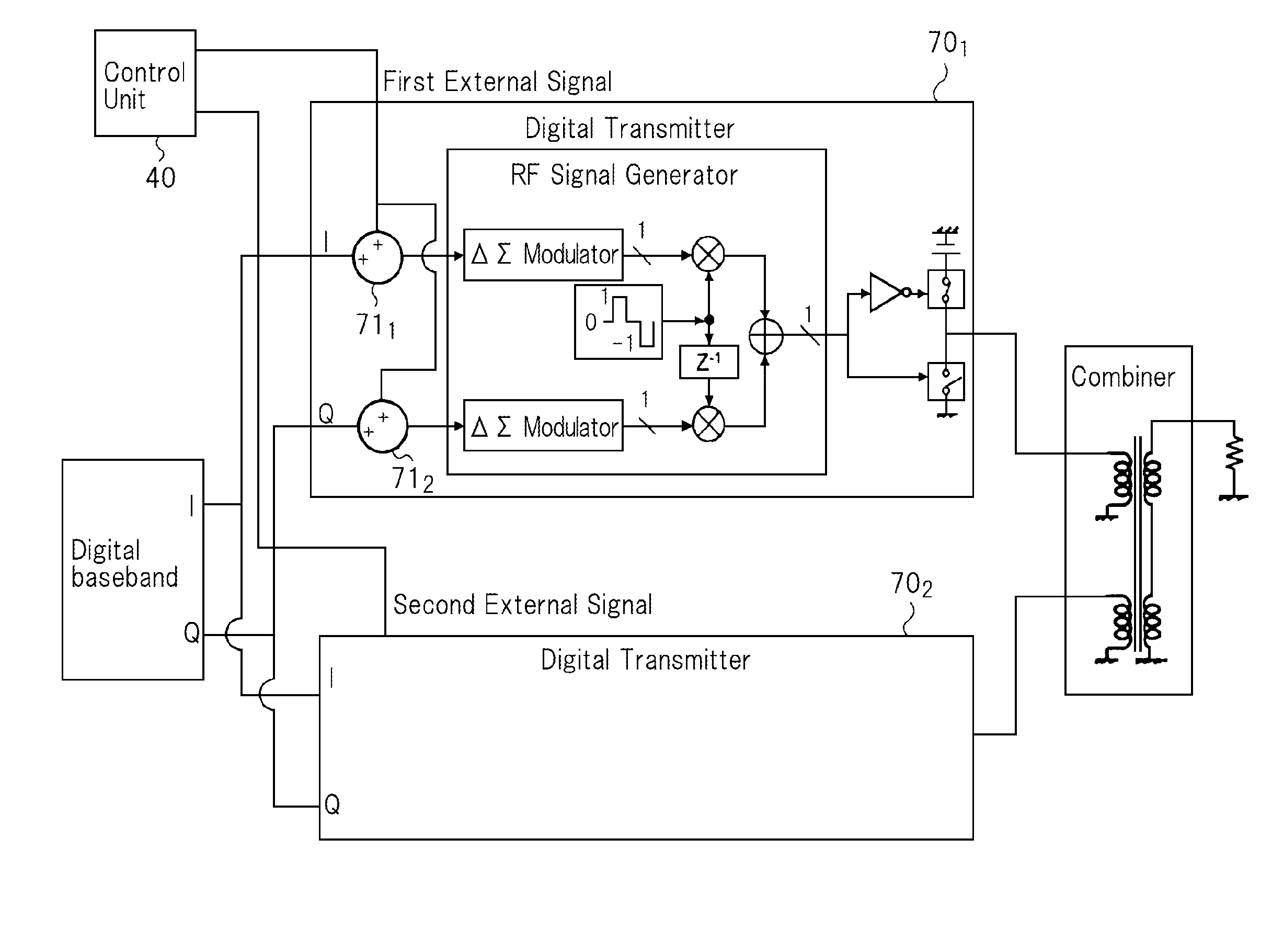
[0122]FIG. 11 is a block diagram showing one configurational example of a transmitter of the third exemplary embodiment.

[0123]The transmitter of the third exemplary embodiment is configured such that in the transmitter shown in FIG. 3, changeover switches 211 and 212 are replaced by adders 711 and 712 so that, instead of the fixed initial values, the first external signal and second external signal generated outside are supplied to the RF signal generator via adders 711 and 712. That is, in the present exemplary embodiment, adders 711 and 712 are used as the input terminals to the ΔΣ modulators in the RF signal generator or the input means for supplying external signals to the internal nodes of the ΔΣ modulators. The first external signal to be input to digital transmitter 701 and the second external signal to be input to digital transmitter 701 should be different from each other. The first external signal and the second external signal are generated a...


PUM


Abstract

A transmitter includes: multiple digital transmitters which perform delta-sigma modulation on the same baseband signal; a combiner that combines the output signals from the plural digital transmitters and outputs the combined result; a control unit that generates an external signal different for every digital transmitter, to be supplied to each of the digital transmitters; and, an input means that supplies the different external signal for every digital transmitter, to the input terminal or the internal node of a delta-sigma modulator that performs the delta-sigma modulation, the delta-sigma modulator being provided for every digital transmitter.

Description

TECHNICAL FIELD[0001]The present invention relates to a transmitter for use in communication and broadcasting equipment such as mobile phone systems, radio LAN (Local Area Network) equipment and others.BACKGROUND ART[0002]Requirements for transmitters used in communication and broadcasting equipment, such as mobile phone systems, radio LAN equipment and others include low power consumption while ensuring that the waveform is maintained at a high accuracy regardless of the transmission power level. In particular, the requirement is that amplifiers transmit power with high efficiency because transmission power amplifiers that are placed at the final stage of the transmitter consume a large amount of power.[0003]Recently, switching amplifiers have attracted attention as power amplifiers that are expected provide high power efficiency. A switching amplifier is assumed to receive pulse waveform signals as its input signals, and amplifies the power of the signal while maintaining the puls...

Claims


Application Information

Patent Timeline
IPC IPC(8): H04B1/04
CPCH04B2001/0408H04B1/04H03F3/195H03F3/211H03F3/245H03F2200/336H03F2200/541H03F3/2173H03F3/24
Inventor HORI, SHINICHIKUNIHIRO, KAZUAKISHIIKUMA, KAZUMI
Owner NEC CORP
Why Eureka
Try Eureka