
Hydraulic driving device for large reel type sprinkler

A drive device, reel-type technology, applied in the direction of fluid pressure actuators, mechanical equipment, servo motors, etc., can solve the problems of cumbersome mechanical transmission mechanisms, large machine volume, unfavorable maintenance, etc., to overcome the driving force of water turbines Insufficient, eliminate recovery speed error, optimize the effect of maintenance process

Active Publication Date: 2019-01-11
CHINA UNIV OF MINING & TECH +1
View PDF5 Cites 3 Cited by
  • Summary
  • Abstract
  • Description
  • Claims
  • Application Information

AI Technical Summary

Problems solved by technology

[0003] Although the reel type sprinkler has the advantages of saving water and high efficiency, the existing reel type sprinkler mainly has the following problems: First, the existing reel drive method uses spray irrigation pressure water to drive the water turbine, which cannot perform large-scale irrigation. Load movement is not suitable for large-scale sprinkler irrigation machines with long PE pipes; second, the accuracy of the existing PE recovery speed detection method is poor, which is not conducive to real-time recovery control of PE pipes; third, the existing mechanical transmission mechanism is cumbersome, making the whole machine Large size and not conducive to later maintenance; Fourth, there is no good failure emergency design, so that the whole machine cannot cope with sudden failures well

Method used


Image

  • Hydraulic driving device for large reel type sprinkler
  • Hydraulic driving device for large reel type sprinkler
  • Hydraulic driving device for large reel type sprinkler

Examples


Embodiment Construction

[0021] The present invention will be described in detail below in conjunction with the accompanying drawings and specific embodiments.

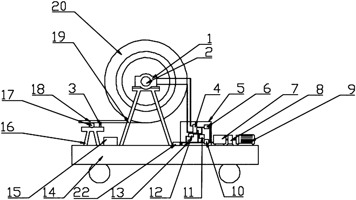
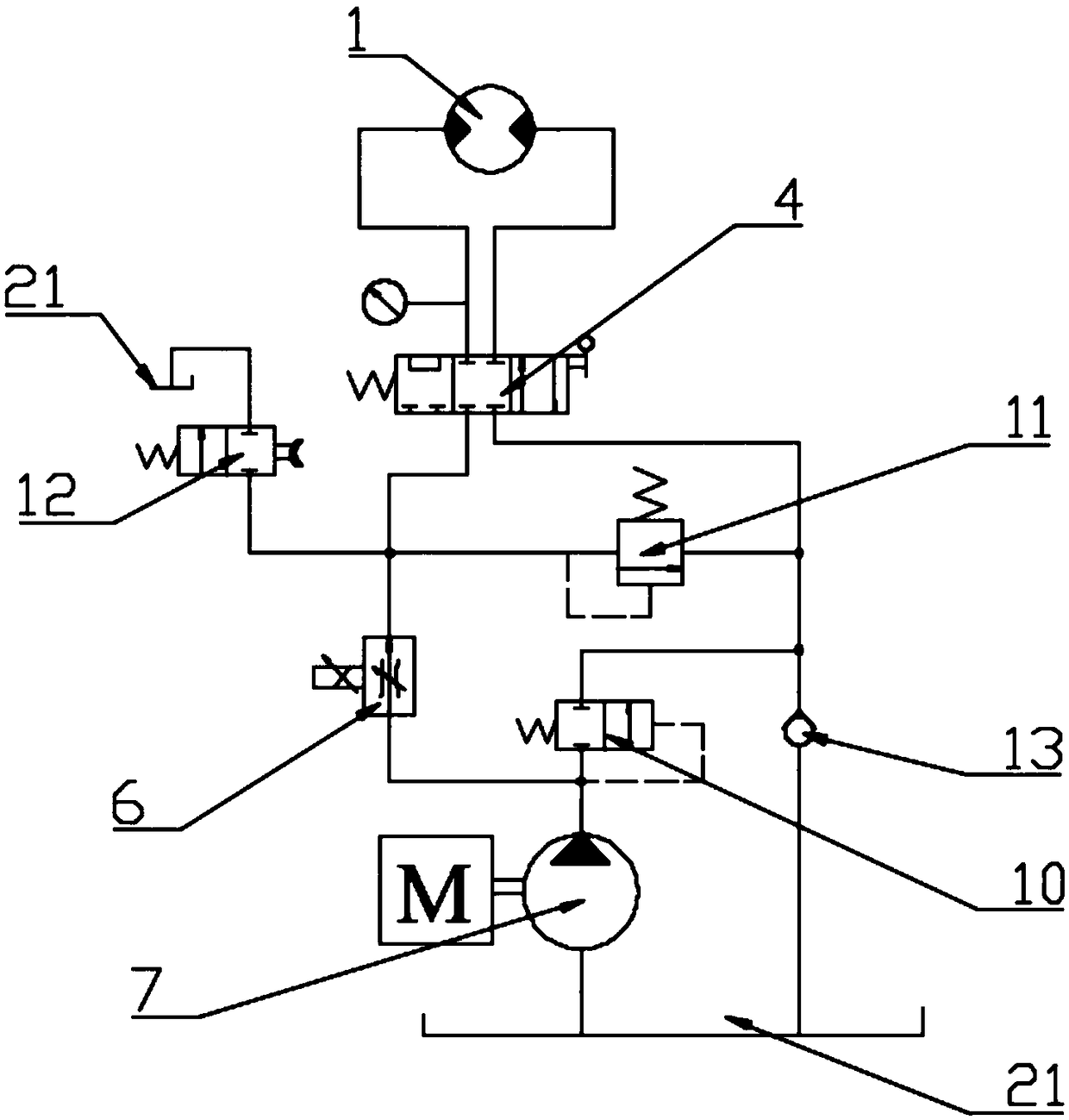
[0022] Such as Figure 1 to Figure 3 As shown, a large-scale reel-type sprinkler hydraulic drive device includes a reel 20 and a PE pipe 18. The reel 20 is supported on the vehicle body 14 of the irrigation machine through a reel support frame 19, and the PE pipe 18 is rotatably wound on the reel On the disk 20, the drive mechanism is connected with the reel shaft and drives the rotation of the reel 20; the drive mechanism includes a hydraulic motor 1 and a hydraulic system, the hydraulic motor 1 is installed on the reel support frame 19, and the output shaft of the hydraulic motor 1 passes through The coupling 2 is connected with the reel shaft; the hydraulic system includes a hydraulic pump 7, a hydraulic valve block 5 and a hydraulic pump driving device, the hydraulic valve block 5 is fixed on the vehicle body 14, and a three-position four...


PUM


Abstract

The invention discloses a hydraulic driving device for a large reel type sprinkler. The driving mechanism comprises a hydraulic motor and a hydraulic system, wherein the hydraulic motor is arranged ona reel support frame; an output shaft of the hydraulic motor is connected to a reel shaft through a coupling; the hydraulic system comprises a hydraulic pump, a hydraulic valve block and a hydraulicpump driving device; the hydraulic valve block is fixed to a vehicle body; a three-position four-way directional control valve, a proportional throttle valve, a one-way valve and a two-position two-way directional control valve are arranged on the hydraulic valve block; the hydraulic pump enables hydraulic oil in an oil tank to sequentially pass oil inlets of the proportional throttle valve and the three-position four-way directional control valve and enter the hydraulic motor; return oil of the hydraulic motor sequentially passes an oil return hole of the three-position four-way directional control valve and the one-way valve and returns to the oil tank; the two-position two-way directional control valve is connected in parallel to an oil line between an oil outlet of the proportional throttle valve and the oil inlet of the three-position four-way directional control valve; and an oil outlet of the two-position two-way directional control valve communicates with the oil tank. The hydraulic driving device can supply relatively large reel driving force, can also accurately detect the recovery speed of PE pipes and meanwhile is simple in structure and low in failure rate.

Description

technical field [0001] The invention relates to a reel-type sprinkler irrigation machine, in particular to a hydraulic drive device for a large-scale reel-type sprinkler irrigation machine, which belongs to the technical field of sprinkler irrigation equipment. Background technique [0002] The reel sprinkler irrigation machine is the most widely used sprinkler irrigation machine. Its principle is to wind the traction PE pipe on the winch, use the sprinkler irrigation pressure water to drive the water turbine to rotate, and then drive the winch to rotate through the transmission device, and pull the sprinkler car to move automatically. And spraying, using special equipment such as nozzles, spray water with a certain pressure into the air to form small water droplets to land, and supply the special machinery for the water demand of crops. Sprinkler irrigation machinery that is installed in one. [0003] Although the reel type sprinkler has the advantages of saving water and ...

Claims


Application Information

Patent Timeline
IPC IPC(8): F15B11/08F15B13/02F15B13/04B65H75/38B65H75/44
CPCB65H75/38B65H75/4481B65H2701/333F15B11/08F15B13/024F15B13/0401
Inventor 朱真才沈刚邱志鹏彭涛江帆汤裕李伟周公博撒韫洁李翔
Owner CHINA UNIV OF MINING & TECH
Learn More