
Eureka
For R&D, Eureka makes reading and utilizing patents & technical documents easy.
Eureka AIR
Designed for self-driven R&D workflows. Generate viable solutions, solve complex R&D challenges, empower your innovation with AI.

Eureka Materials
Designed for material experts only. Revolutionize your material R&D, from search, analyze, to developing new materials.

TechResearch
Generate reliable direction feasibility study reports for your R&D in just a few steps.

TechSeek
Discover and master advanced knowledge NOW. Basics, ideas, possibilities, all at once.

TechMind
As an expert in R&D Theories, TechMind can generates customized viable solutions instantly.

TechRisk
Analyze your overall solution with one click, know your potential R&D risks in advance.

TechMonitor
Get weekly tech updates, stay abreast of the latest tech innovations and key insights.
Remotely controlled valve
- Summary
- Abstract
- Description
- Claims
- Application Information
AI Technical Summary
Benefits of technology
Problems solved by technology
Method used
Image

Examples
Example
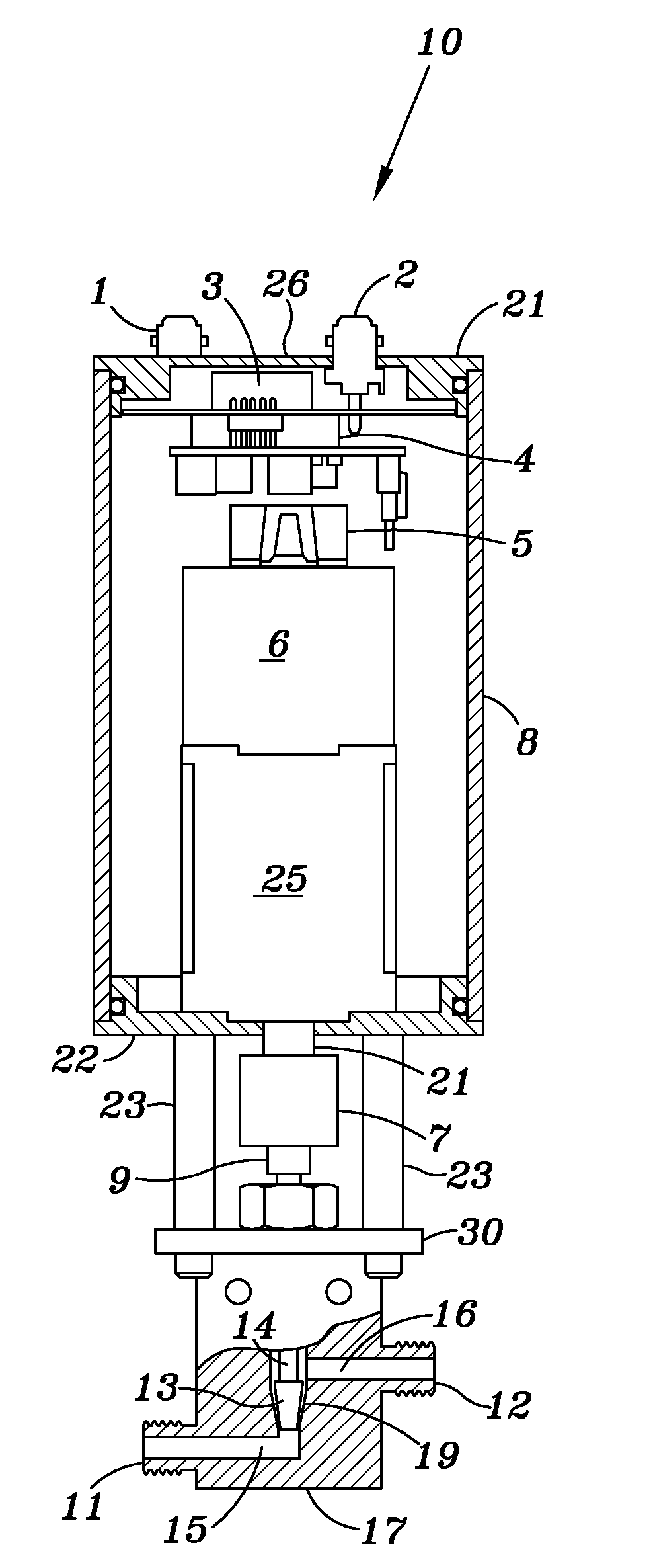
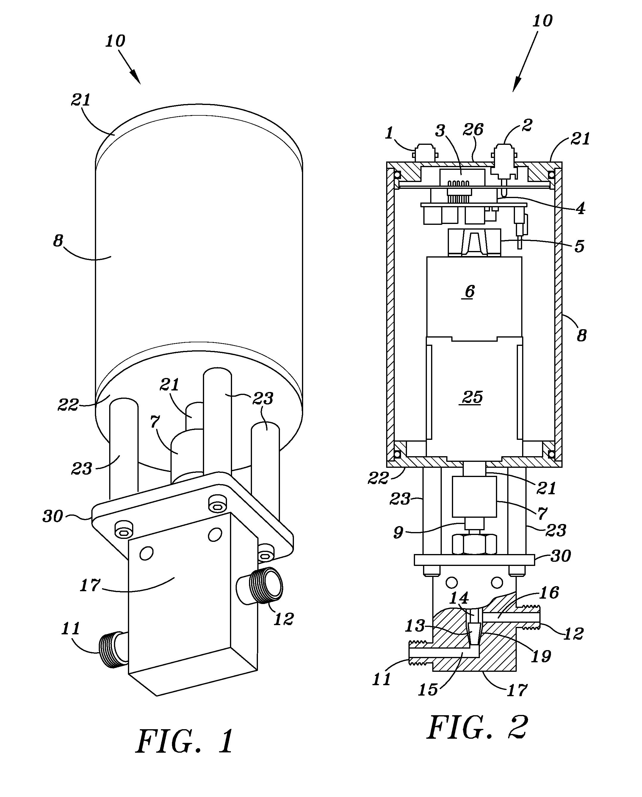
[0010]An embodiment of the valve 10 of the present invention is shown in FIG. 1 and includes a cylindrical housing 10 having a top cover plate 21 and a bottom cover plate 22. Housing 10 contains the control module, electric motor and transmission for moving the valve stem 14 all of which is shown in FIG. 2. The valve 10 also includes a valve body 17 which is attached to the bottom cover plate 22 by a plurality of studs 23.
[0011]The transmission includes an output shaft 21 which is connected to the valve stem 14 via a coupler 7 and 9 which causes the valve stem 14 to reciprocate to thereby cause the valve to be opened or closed.
[0012]As shown in FIG. 2, the internal components of the valve include a motor 6 and a transmission 25 coupled to the motor. Transmission 25 includes an output shaft 21. A coupler 7 couples the output shaft of the transmission to spline 9 which is also coupled to the valve stem 14.
[0013]A similar arrangement for raising and lowering a valve stem is shown in U....
PUM
 Abstract
Description
Claims
Application Information
 - R&D Engineer
- R&D Manager
- IP Professional
- Industry Leading Data Capabilities
- Powerful AI technology
- Patent DNA Extraction
Browse by: Latest US Patents, China's latest patents, Technical Efficacy Thesaurus, Application Domain, Technology Topic, Popular Technical Reports.
© 2024 PatSnap. All rights reserved.Legal|Privacy policy|Modern Slavery Act Transparency Statement|Sitemap|About US| Contact US: help@patsnap.com