Method, apparatus and article for detection of transponder tagged objects, for example during surgery

a technology of transponder and object, applied in the field of methods, can solve the problems of inefficient manual approach, additional surgery, and serious adverse medical consequences

Active Publication Date: 2015-10-01
TYCO HEALTHCARE GRP LP
View PDF8 Cites 40 Cited by
  • Summary
  • Abstract
  • Description
  • Claims
  • Application Information

AI Technical Summary

Benefits of technology

[0019]The delay period for each of the number of subsamples may be between zero seconds and the nominal tag response signal period. The delay period for at least one of the number of subsamples may have a duration between the nominal tag response signal period and twice the nominal tag response signal period. For each successive pair of subsamples, the delay period associated with a first successive one of the pairs of subsamples may be less than the delay period associated with a next successive one of the pairs of subsamples. For each successive pair of subsamples, the delay period associated with a first successive one of the pairs of subsamples may be less than the delay period associated with a next successive one of the pairs of subsamples by a duration approximately equal to the nominal tag response signal period divided by the number of subsamples. The delay period associated with each subsample may differ from the delay period for the other subsamples by less than the nominal tag response signal period. The delay period associated with each subsample may be approximately an integer multiple of the nominal tag response signal period divided by the number of subsamples. During each of the plurality of interrogation cycles in each of the number of subsamples, before the receive response portion of the interrogation cycle, the processor may further: wait a fixed recovery time after the transmit portion of the interrogation cycle, the fixed recovery time having a duration determined to provide synchronization between the transmit portion and the receive response portion of each interrogation cycle. The transponder detection device may further include: a plurality of antennas operatively coupled to the antenna, and the processor may further: obtain a number of subsamples for each of the plurality of antennas. The processor may further: determine the presence or absence of a transponder based at least in part on a number of measurements of the electromagnetic signals received during the plurality of interrogation cycles of at least one of the number of subsamples. The processor may further: determine the presence or absence of a transponder based at least in part on a frequency of the electromagnetic signals received during the interrogation cycle being within a defined frequency range. The defined frequency range may extend from about 137 kHz to about 160 kHz. The processor may further: determine the presence or absence of a transponder based at least in part on a Q value of the electromagnetic signals received during the interrogation cycle. The processor may further: determine the presence or absence of a transponder based at least in part on a Q value of the electromagnetic signals received during the interrogation cycle being at least equal to a threshold Q value. The threshold Q value may be 35. The processor may further: determine the presence or absence of a transponder based at least in part on a signal detection threshold. The processor may further: determine whether at least two of the number of subsamples are above a signal detection threshold. The processor may further: receive electromagnetic signals during a noise detection portion; determine a noise value indicative of a noise level that corresponds to a number of measurements of the electromagnetic signals received during the noise detection portion; adjust a signal detection threshold based at least in part on the determined noise value; and determine the presence or absence of a transponder based at least in part on a number of measurements of the electromagnetic signals received during the plurality of interrogation cycles of at least one of the number of subsamples and the adjusted signal detection threshold. The processor may further: compare a maximum value of a plurality of matched filter outputs with the adjusted signal detection threshold. The processor may further: adjust the signal detection threshold to be approximately twice the determined noise value. The processor may further: determine if an output of at least one matched filter during the noise detection portion exceeds a noise fault threshold indicative of a noise fault. The electromagnetic interrogation signal may be in at least one of a 136 kHz band, a 139 kHz band, a 142 kHz band, a 145 kHz band, a 148 kHz band, a 151 kHz band or a 154 kHz band. The processor may further: ignore any electromagnetic signals received during a recovery portion of the interrogation cycle that precedes the receive response portion of the interrogation cycle. The transponder detection device may further include: an antenna circuit coupled to the antenna; wherein the processor may further cause energy to be dumped from the antenna circuit during a dump portion of the interrogation cycle that precedes the recovery portion of the interrogation cycle. The electromagnetic signals received during the receive response portion of the interrogation cycle may be unmodulated electromagnetic signals.

Problems solved by technology

Failure to locate an object before closing the patient may require additional surgery, and in some instances may have serious adverse medical consequences.
Such a manual approach is inefficient, requiring the time of highly trained personnel, and is prone to error.
However, inexpensive transponders typically have a relatively large variation in the frequency of signals they emit, making it difficult to accurately detect the signals returned by the transponders.
This may be particularly difficult in some environments which are noisy with respect to the particular resonant frequencies of the transponders.

Method used


Image

  • Method, apparatus and article for detection of transponder tagged objects, for example during surgery
  • Method, apparatus and article for detection of transponder tagged objects, for example during surgery
  • Method, apparatus and article for detection of transponder tagged objects, for example during surgery

Examples


Embodiment Construction

[0047]In the following description, certain specific details are set forth in order to provide a thorough understanding of various disclosed embodiments. However, one skilled in the relevant art will recognize that embodiments may be practiced without one or more of these specific details, or with other methods, components, materials, etc. In other instances, well-known structures associated with transmitters, receivers, or transceivers have not been shown or described in detail to avoid unnecessarily obscuring descriptions of the embodiments.

[0048]Unless the context requires otherwise, throughout the specification and claims which follow, the word “comprise” and variations thereof, such as, “comprises” and “comprising” are to be construed in an open, inclusive sense, that is as “including, but not limited to.”

[0049]Reference throughout this specification to “one embodiment” or “an embodiment” means that a particular feature, structure or characteristic described in connection with ...


PUM


Abstract

The presence or absence of objects is determined by interrogating or exciting transponders coupled to the objects using pulsed wide band frequency signals. Interrogation is broken down into a number of subsample scan cycles each having interrogation cycles a start time forward in time by a fraction of a period of an expected transponder response signal. Ambient or background noise is evaluated and a threshold adjusted based on the level of noise. Adjustment may be based on multiple noise measurements or samples. Noise detection may be limited, with emphasis placed on interrogation to increase the signal to noise ratio. Matched filtering may be employed. Presence/absence determination may take into account frequency and/or Q value to limit false detections. Appropriate acts may be taken if detected noise is out of defined limits of operation, for example shutting down interrogation and/or providing an appropriate indication.

Description

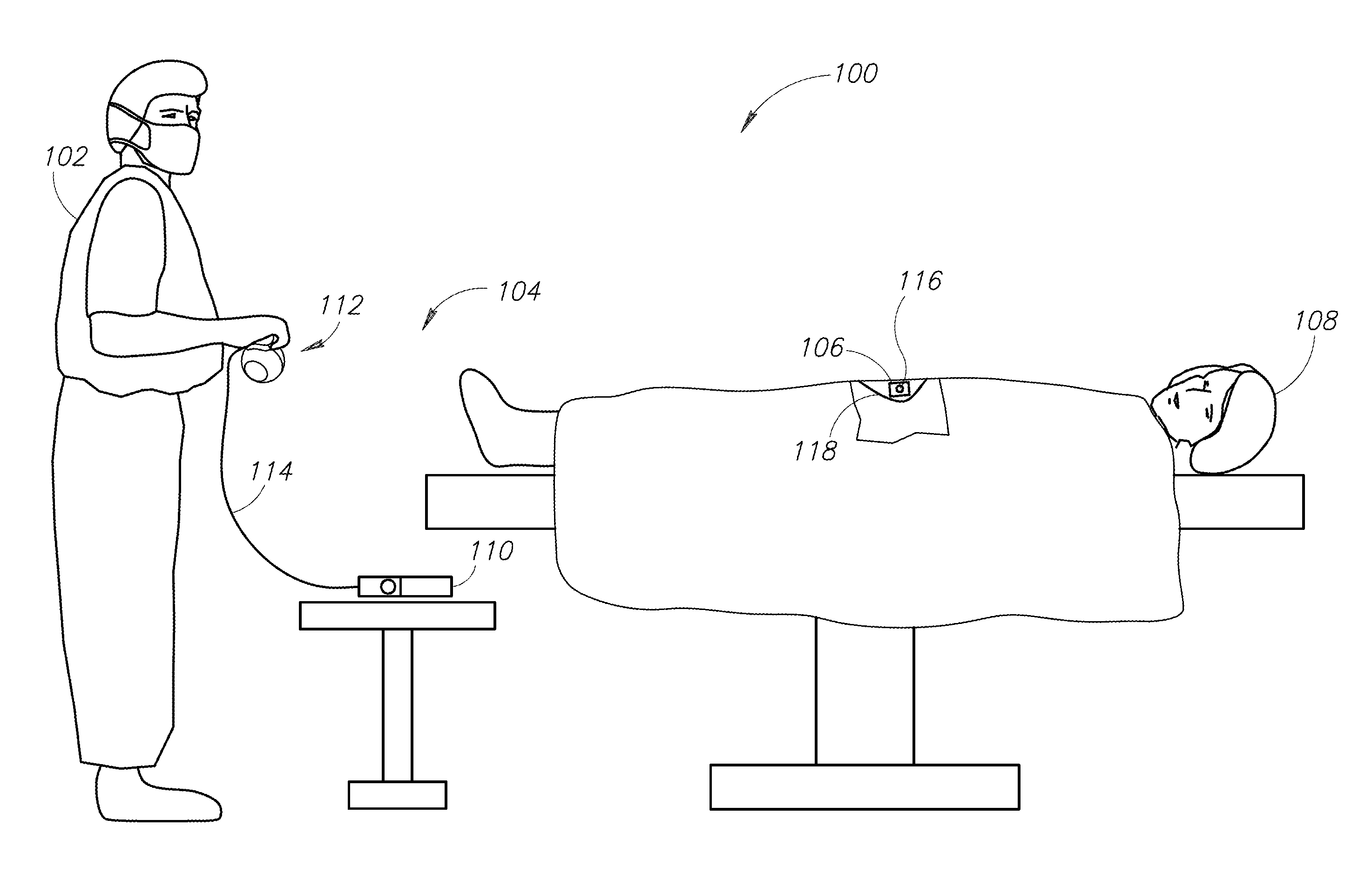
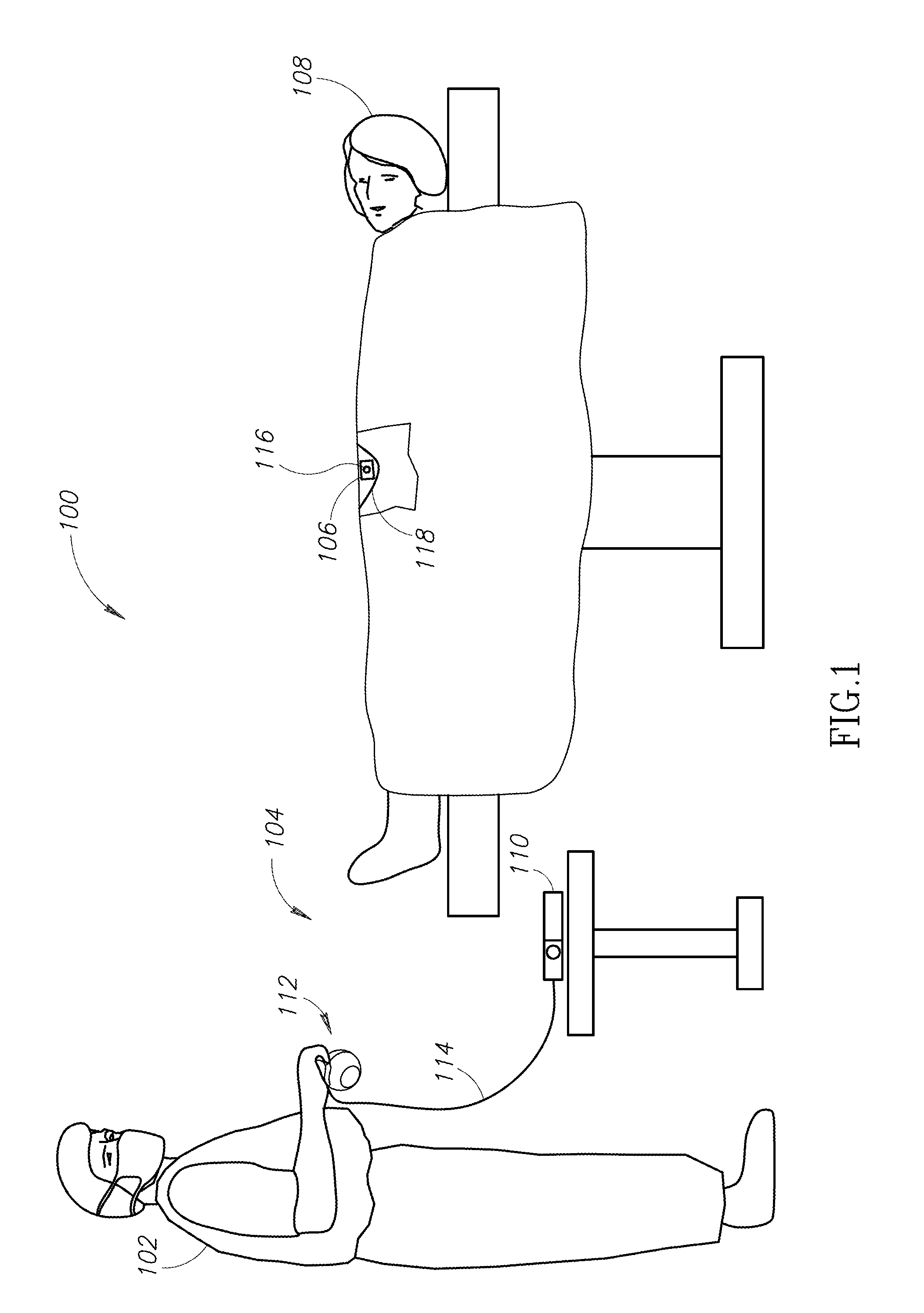
BACKGROUND[0001]1. Field[0002]This disclosure generally relates to the detection of the presence or absence of objects tagged with transponders, which may, for example, allow the detection of surgical objects during surgery.[0003]2. Description of the Related Art[0004]It is often useful or important to be able to determine the presence or absence of an object.[0005]For example, it is important to determine whether objects associated with surgery are present in a patient's body before completion of the surgery. Such objects may take a variety of forms. For example, the objects may take the form of instruments, for instance scalpels, scissors, forceps, hemostats, and / or clamps. Also for example, the objects may take the form of related accessories and / or disposable objects, for instance surgical sponges, gauzes, and / or pads. Failure to locate an object before closing the patient may require additional surgery, and in some instances may have serious adverse medical consequences.[0006]S...

Claims


Application Information

Patent Timeline
Patent Type & Authority Applications(United States)
IPC IPC(8): A61B19/00G06K7/10
CPCA61B19/44G06K7/10039A61B2019/448G06K2007/10524G06K7/10386G01V15/00A61B5/061A61B2505/05A61B90/90A61B90/98G06K7/10356G06K7/10366
Inventor BLAIR, WILLIAM A.POIRIER, DAVID A.CRUMP, CURTIS
Owner TYCO HEALTHCARE GRP LP
Why Eureka
Try Eureka