Method for handling material in a material conveying system, input point of a material conveying system, and a material conveying system

a conveying system and material technology, applied in the field of pneumatic material conveying systems, can solve the problems of inability to economically viable equip with their own partial vacuum generation apparatus or with a separate container, litter bins in parks and public spaces are emptied too rarely, and objects are put, so as to avoid drawbacks of prior art, effective and structurally simple solution, efficient management

Inactive Publication Date: 2015-10-01
MARICAP OY
View PDF0 Cites 4 Cited by
  • Summary
  • Abstract
  • Description
  • Claims
  • Application Information

AI Technical Summary

Benefits of technology

[0015]The solution according to the invention has a number of important advantages. By means of the solutions of the invention the drawbacks of prior art are avoided. In the solution according to the invention an input point that is surprisingly simple in terms of its means can be applied, the connection of the input aperture of which input point to the conveying pipe opens and closes automatically as a result of the suction produced by a partial-vacuum source and of the wall that changes its shape. In this case also the access of replacement air via the input aperture is limited automatically. The method, input point and system according to the invention do not require complex valve arrangements in connection with the input points. With the solution according to the invention the waste management of public spaces, e.g. parks, can be efficiently managed, in which case when replacing conventional litter bins with input points according to the invention the manual emptying of litter bins is avoided and at the same time the manual handling of possible dangerous objects in connection with emptying is avoided. The wall changing its shape of the solution according to the invention is preferably tubular, through which the channel between an input aperture and the conveying pipe runs. An aperture or apertures are formed in the envelope functioning as the frame of an input point, the air pressure surrounding which aperture or apertures is able to act on the wall that changes its shape from the outside of it. With the solution according to the invention an effective and structurally simple solution for constricting and closing the channel between an input point and a conveying pipe is achieved. The solution according to the invention is well suited for use in connection with different types of pneumatic material conveying systems. The material collection container of the system can be fixed or it can be a transportation container or a so-called deep collection container-separating device. By using a deep collection container as a separating device, the material conveyed into the collection container can be efficiently stored, and emptying of the container can be performed less frequently. Emptying of the collection container can be performed by lifting the collection container and by transferring the material that has collected in the container from an openable and closable aperture arranged in the bottom part of the container into the container of a transportation means, such as of a garbage truck. The transportation means can comprise a press for compressing the material so it becomes denser and a hoist for lifting the collection container. With the solution according to the invention, the separating device of a pneumatic pipe transport system for material and the collection container intended for temporary storage of the transported material can be efficiently combined. When the collection container is a so-called deep collection container, which is at least partly embedded below the surface level of the ground, or corresponding surface level, the space requirement can be efficiently reduced. According to one preferred embodiment the deep collection container-separating device comprises a collection container and an external container, into which the collection container is arranged and from which the collection container is lifted for emptying. A mobile partial-vacuum generating apparatus can be used effectively in connection with the material conveying system of the invention to achieve the partial vacuum needed in the pneumatic transportation of material. In this case a dedicated fixed partial-vacuum generating apparatus is not needed in individual material conveying systems. The system thus enables the division of effective operating time of the partial-vacuum source between many material conveying systems. The system also enables the offering of the partial-vacuum source of a material conveying system as a service to properties. In addition, the invention enables an effective way to ensure material conveying by using many mobile partial-vacuum sources, in which case e.g. in a malfunction situation a primary partial-vacuum source can easily be replaced with a second mobile backup apparatus. The mobile partial-vacuum source according to the invention fits to function in more cramped locations also because it can be arranged in a vehicle, in which space for wastes is not needed at the same time. The solution according to the invention effectively enables a different frequency for the operation of the partial-vacuum source and for the emptying of a container.

Problems solved by technology

On the other hand, there are a lot of quite small sites, such as office properties, commercial properties, industrial properties and especially residential properties or other sites, in which it is desired to achieve a pneumatic pipe transport solution for wastes, but which are not economically viable to equip with their own partial-vacuum generating apparatus or with a separating device and a separate container.
Additionally, one problem is that the litter bins in parks and public spaces are emptied too seldom.
Another problem is also that objects are put into them, which can be problematic for the personnel manually emptying them, such as sharp objects, e.g. syringes used for drugs or corresponding.
In prior-art solutions the input points for material often have complex valve arrangements with which the connection of an input point to the conveying piping and / or the access of replacement air from an input point into the conveying piping is controlled.
In many cases complex input point arrangements are undesirable.

Method used


Image

  • Method for handling material in a material conveying system, input point of a material conveying system, and a material conveying system
  • Method for handling material in a material conveying system, input point of a material conveying system, and a material conveying system
  • Method for handling material in a material conveying system, input point of a material conveying system, and a material conveying system

Examples


Embodiment Construction

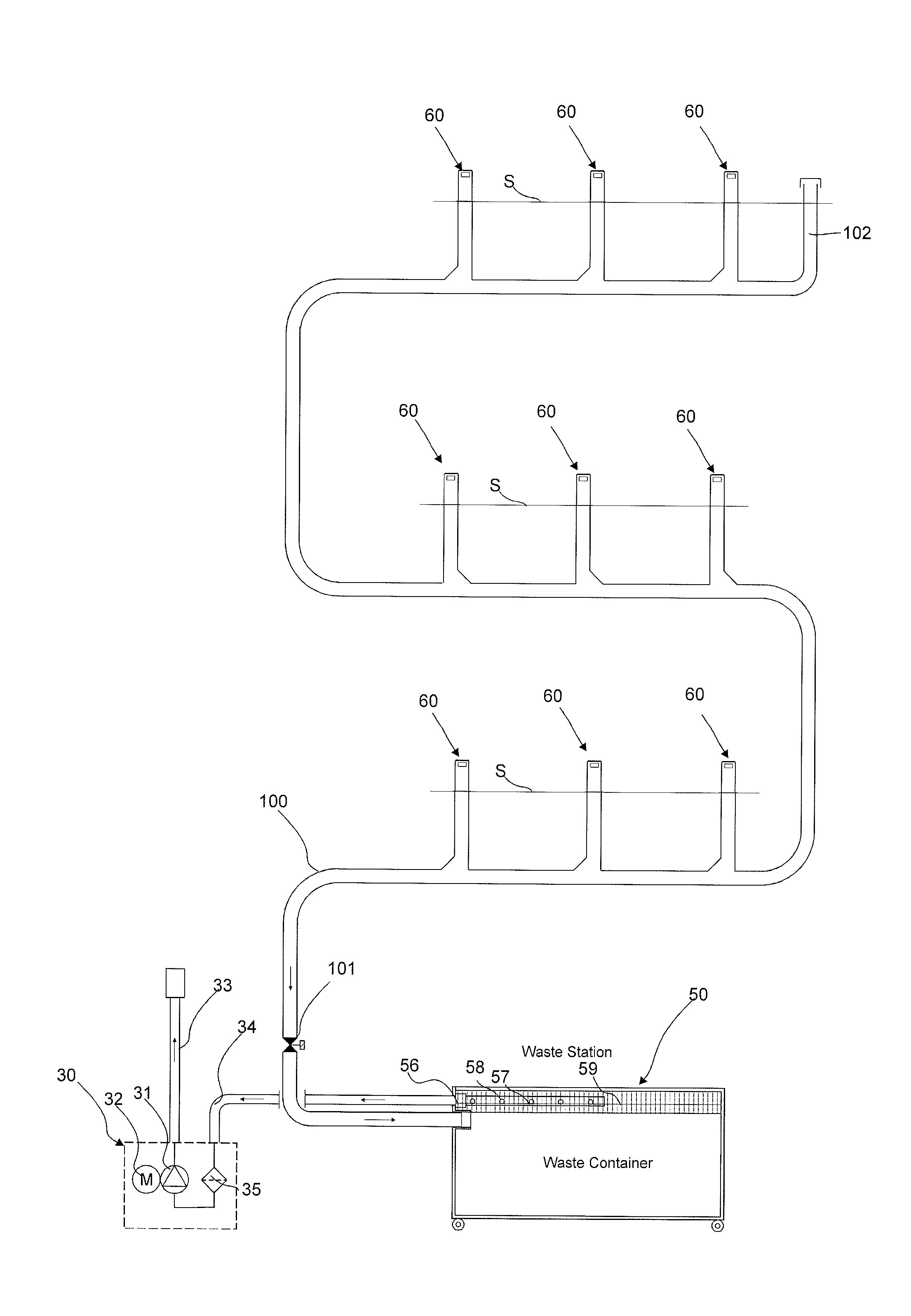
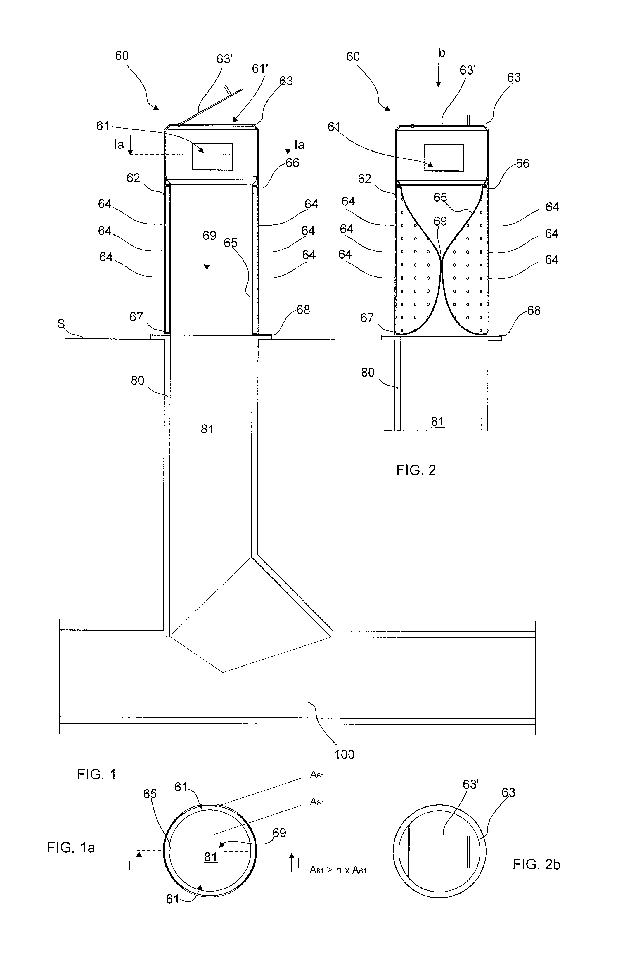
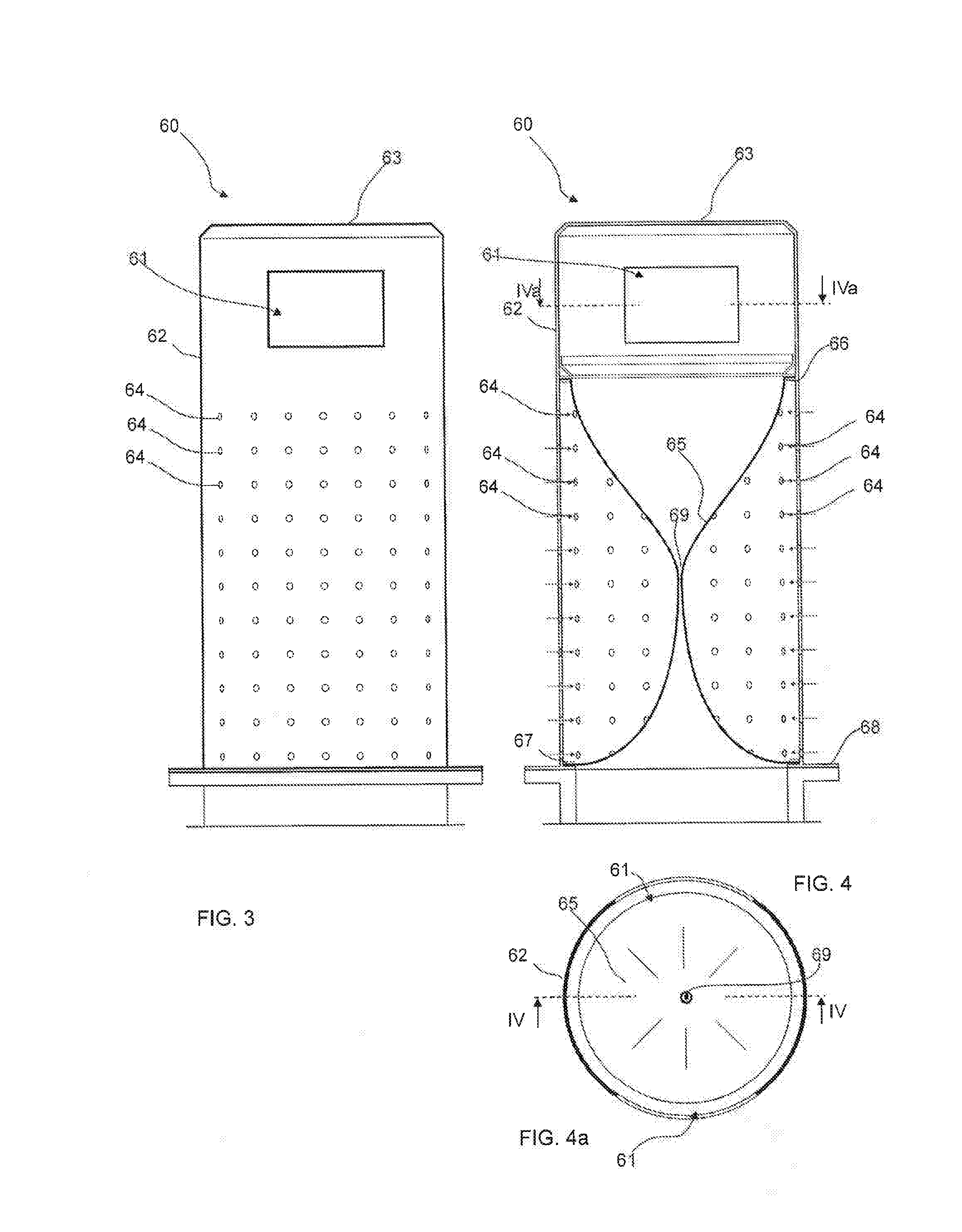
[0029]FIGS. 1-4 present a part of a pneumatic material conveying system, which part comprises a material conveying pipe 100, along the side of which at least one, typically many, input points 60 are arranged. An input point 60 is a feed-in station for material, more particularly of waste material, intended to be transported, from which station the material, more particularly waste material, such as litter, household waste, or recyclable material intended to be transported, is fed into the conveying system. An input point 60 can also be a refuse chute, into which material is fed from input apertures on different floors of a building. The system can comprise a number of input points 60, from which the material intended to be transported is fed into conveying piping 100, 100A, 100B, 100C. An input point 60 is connected to the conveying pipe 100 or to an input pipe 80 in connection with it. Inside the input pipe is a feed-in channel 81, which extends to the conveying pipe 100. In the fi...


PUM


Abstract

Method for feeding and transporting material in a pneumatic material conveying system includes an input point connected to a material conveying pipe and a material container, wherein the material to be transported is separated from the transporting air. A partial vacuum/pressure difference and/or a transporting air flow is achieved in the conveying pipe at least during the transporting of material. The suction side of the partial-vacuum source is connected to the conveying pipe and onwards to an input point arranged in the conveying pipe or at least to the feed-in channel that is between the conveying pipe and an input point, wherein the input point, or at least the feed-in channel, that is closest to the material container in the conveying direction of the material empties and the material displaces into the conveying pipe. A wall for closing the pathway between an input aperture and the conveying pipe is provided.

Description

BACKGROUND OF THE INVENTION[0001]The object of the invention is a method as defined in the preamble of claim 1.[0002]The object of the invention is also an input point, according to claim 8, of a material conveying system.[0003]The object of the invention is also a material conveying system according to claim 19.[0004]The invention relates generally to pneumatic material conveying systems, such as to partial-vacuum transporting systems, more particularly to the collection and conveying of wastes, such as to the conveying of household wastes and litter.[0005]Systems wherein wastes are conveyed in piping by means of suction and / or transporting air are known in the art. In these, wastes are moved long distances in the piping pneumatically, by means of suction and / or a pressure difference, together with the transporting air. The apparatuses are used for, among other things, the conveying of wastes in different institutions, for the conveying of household waste or for the conveying of ot...

Claims


Application Information

Patent Timeline
Patent Type & Authority Applications(United States)
IPC IPC(8): B65F5/00B65F1/12B65G53/40B65G53/26B65F1/10
CPCB65F5/005B65G53/26B65F1/125B65G53/40B65F1/105B65F1/1447F16K7/07B65G53/10F16K7/02F16L55/105F16L55/12B65F5/00
Inventor SUNDHOLM, GORAN
Owner MARICAP OY
Why Eureka
Try Eureka