Gusset plate connection in bearing of beam to column

a technology of gusset plate and beam, which is applied in the direction of structural elements, shock-proofing, building components, etc., can solve the problems of fractured welds, cracks in the column flange and column web, and uncertain practice of welding the beam's flanges directly to the column

Active Publication Date: 2015-10-01
MITEK HLDG INC
View PDF1 Cites 35 Cited by
  • Summary
  • Abstract
  • Description
  • Claims
  • Application Information

AI Technical Summary

Benefits of technology

[0009]In one aspect, a joint connection structure of a building framework generally comprises a column assembly including a column having a longitudinal axis and a pair of gusset plates connected to the column on opposite sides of the column and extending laterally outward from the column. The bearing elements are operatively connected to the gusset plate and project from the gusset plate. The bearing elements each have an exterior bearing engagement surface. A beam assembly includes a beam having a longitudinal axis, upper and lower flanges, an end portion received between the gusset plates, and at

Problems solved by technology

Experience has shown that the practice of welding the beam's flanges directly to the column is uncertain and/or unsuitable for resistance to earthquakes, explosions, tornadoes and other disastrous events.
Such connection means and welding practice has resulted in sudden, fractured welds, the pulling of divots from the face of the column flange, cracks in the column flange and column web, and various other failures.
Such highly-restrained welds do not provide a rel

Method used


Image

  • Gusset plate connection in bearing of beam to column
  • Gusset plate connection in bearing of beam to column
  • Gusset plate connection in bearing of beam to column

Examples


first embodiment

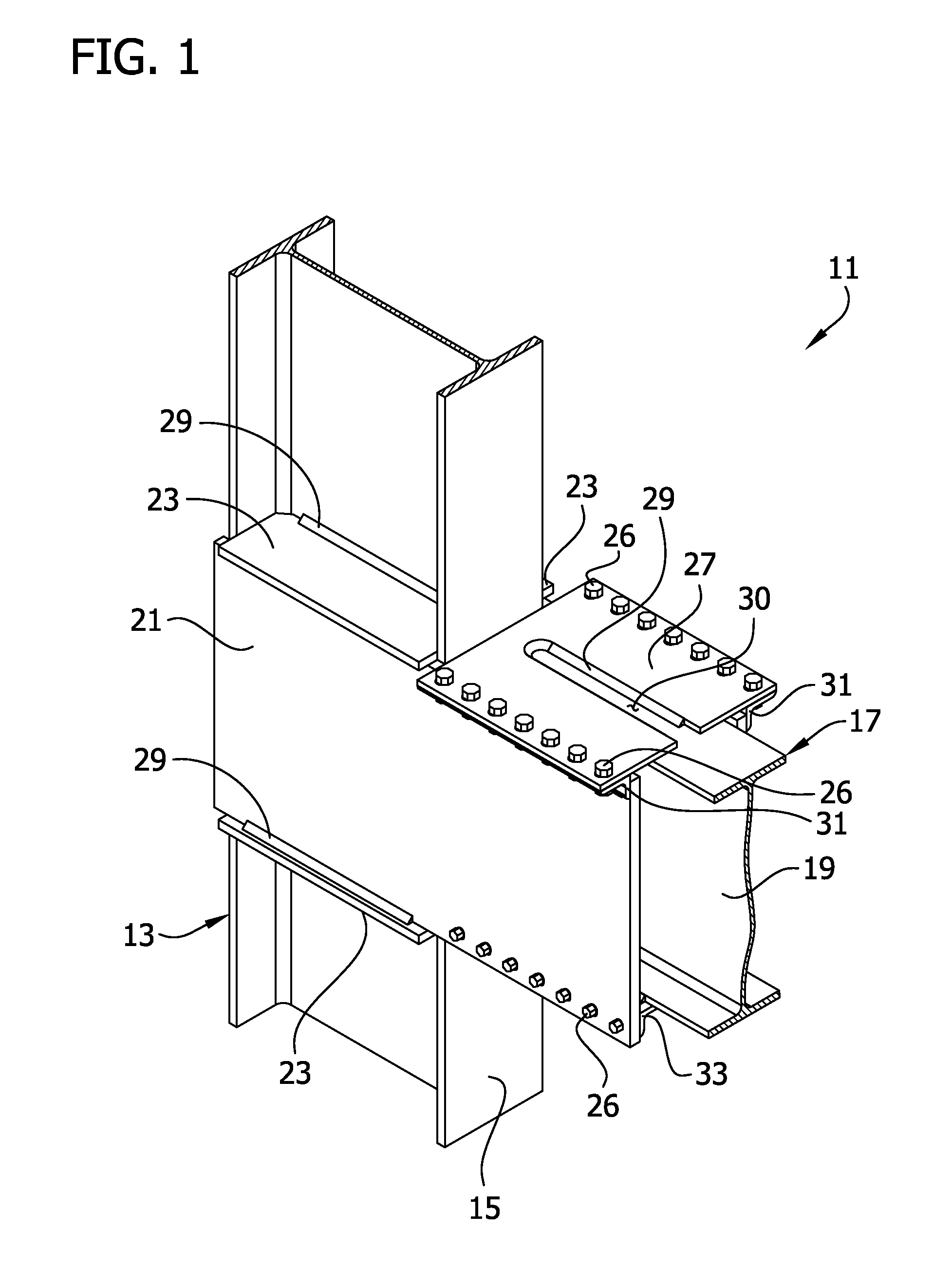
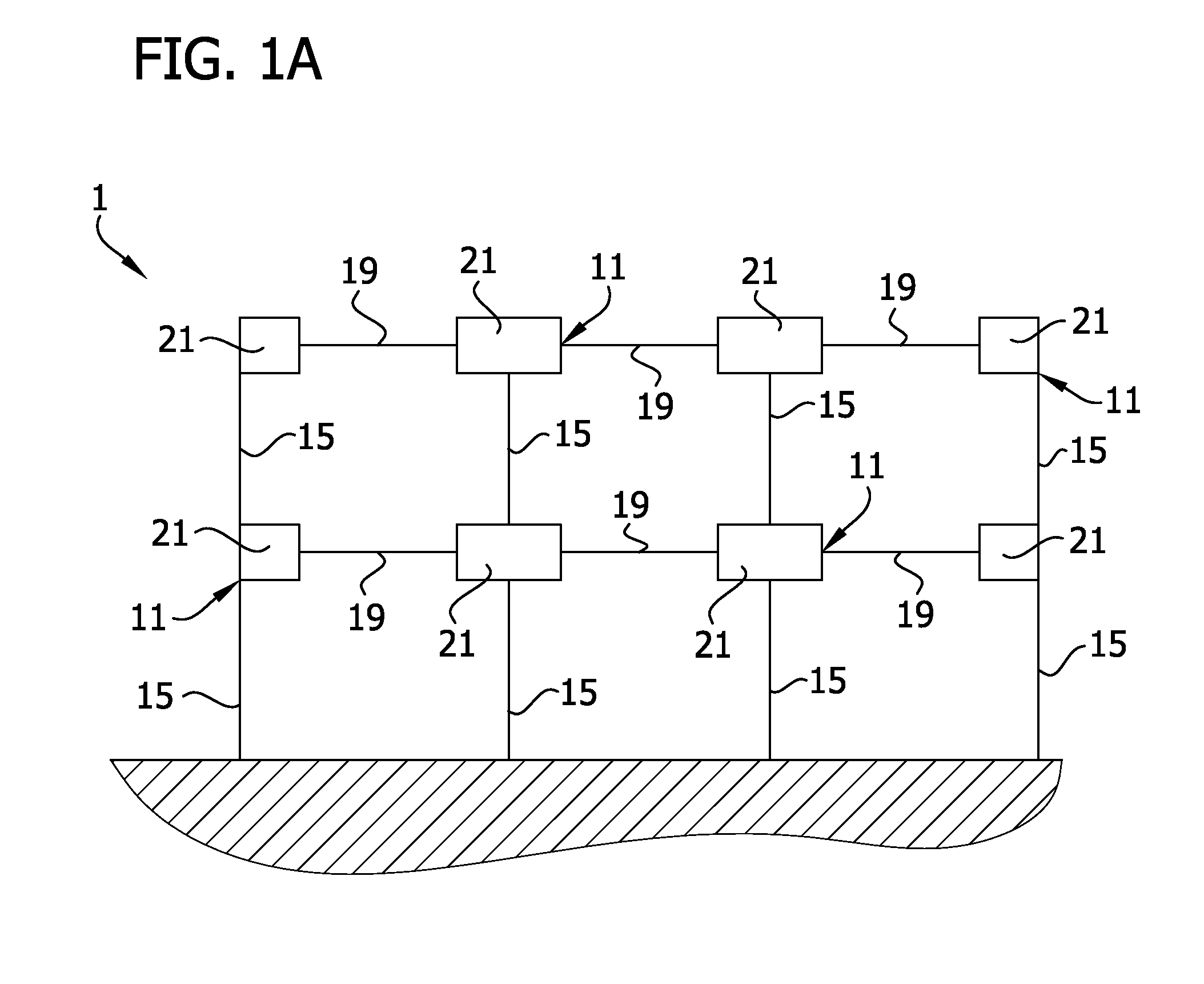
[0194]Referring to FIGS. 1-12, a beam-to-column moment-resisting joint connection structure of a first embodiment is generally indicated at 11. The joint connection structure may be used in the construction of a building framework F (see FIG. 1A). In the illustrated embodiment, the joint connection joins a column assembly 13 including a column 15 to a full-length beam assembly 17 including a full-length beam 19. A full-length beam is a beam that has a length sufficient to extend substantially the full-length between adjacent columns in a structure. Thus, a stub and link beam assembly as shown in FIGS. 5 and 16 of U.S. Pat. No. 6,138,427, herein incorporated by reference, is not a full-length beam. It is understood that the joint connection structure may be a beam-to-column type as shown, or a beam-to-column-to beam type as shown in U.S. Pat. No. 8,146,322, herein incorporated by reference, depending upon the location of the joint connection structure within a building's framework.

[0...

fifth embodiment

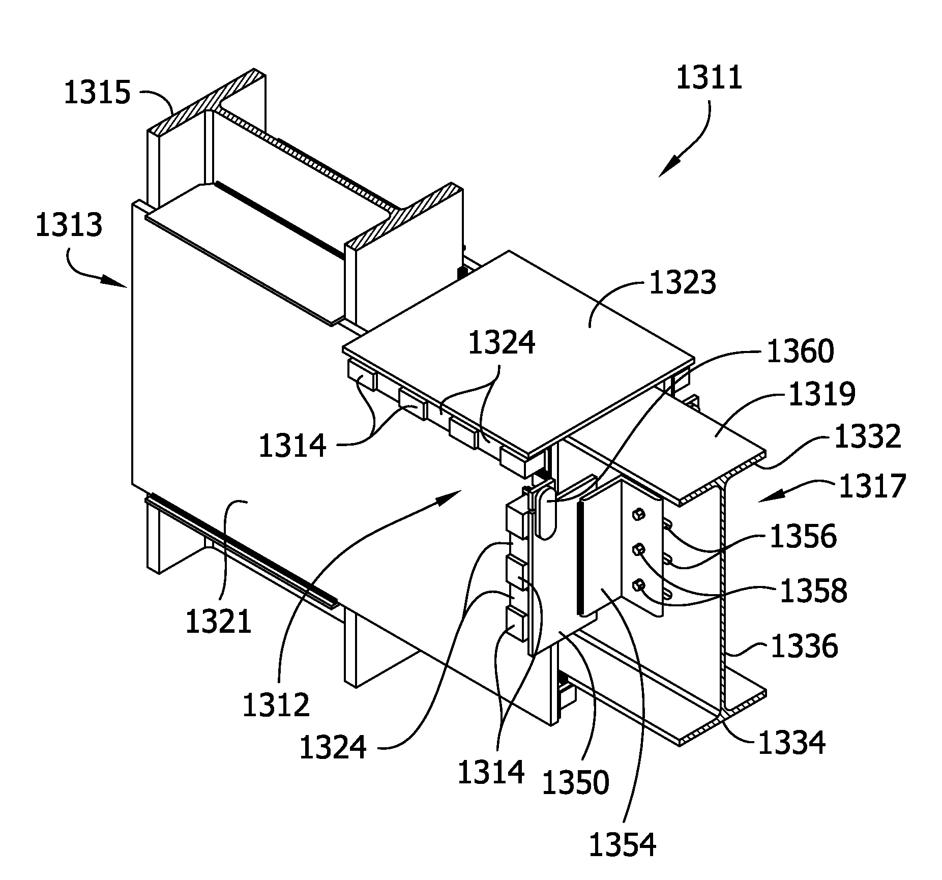
[0216]Referring to FIGS. 49-60, a beam-to-column moment-resisting joint connection structure of a fifth embodiment is generally indicated at 411. The joint connection structure may be used in the construction of a building framework. In the illustrated embodiment, the joint connection joins a column assembly 413 including a column 415 to a full-length beam assembly 417 including a full-length beam 419.

[0217]A spaced apart pair of parallel, vertically and horizontally extending gusset plates 421 sandwich the column 415 and beam 419. Four horizontal shear plates 423 (only three are shown in FIG. 49) are arranged in vertically spaced pairs generally aligned at top and bottom edges of the gusset plates 421. Two angle irons (broadly, “connecting members”) 425A are disposed on an upper flange of the beam 419 at an end of the beam. The angle irons 425A are horizontally spaced from one another and extend along a length of the beam 419. The angle irons 425A connect the gusset plates 421 to t...

sixth embodiment

[0224]Referring to FIGS. 61-72, a beam-to-column moment-resisting joint connection structure of a sixth embodiment is generally indicated at 511. The joint connection structure may be used in the construction of a building framework. In the illustrated embodiment, the joint connection structure 511 joins a column assembly 513 including a column 515 to a full-length beam assembly 517 including a full-length beam 519.

[0225]A spaced apart pair of parallel, vertically and horizontally extending gusset plates 521 sandwich the column 515 and end of beam 519. Four optional horizontal shear plates 523 (only three are shown in FIG. 61) are arranged in vertically spaced pairs generally aligned at top and bottom edges of the gusset plates 521. Two angle irons (broadly, “connecting members”) 525 are disposed on an upper flange of the beam 519 at an end of the beam. The angle irons 525 are horizontally spaced from one another and extend along a length of the beam 519. The angle irons 525 connect...


PUM


Abstract

A beam to column joint connection structure of a building framework has a column assembly and a beam assembly. The column assembly includes a column, a pair of gusset plates on opposite sides of the column, and bearing elements. The beam assembly includes a beam having an end portion received between the gusset plates. The beam assembly has bearing elements. The bearing elements are positioned with respect to each other to prevent movement of the beam assembly relative to the column assembly by engagement of exterior bearing engagement surfaces of the bearing elements of the column assembly with exterior engagement bearing surfaces of the bearing elements of the beam assembly in a direction along a longitudinal axis of the beam. The beam-to-column joint connection does not require any bolts or welds connecting the beam assembly to the column assembly, resulting in an all bearing moment connection.

Description

CROSS-REFERENCE TO RELATED APPLICATIONS[0001]This application is a continuation-in-part of U.S. patent application Ser. No. 14 / 233,953, filed Jan. 21, 2014 and titled GUSSET PLATE CONNECTION OF BEAM TO COLUMN, which is the U.S. national phase entry of PCT application No. PCT / US2013 / 072368, filed Nov. 27, 2013. This application and the '953 application also claim the benefit of priority under 35 U.S.C. §119 to U.S. Patent Application No. 61 / 732,015, titled GUSSET PLATE CONNECTION OF BEAM TO COLUMN, which was filed on Nov. 30, 2012, and U.S. Patent Application No. 61 / 798,041, titled GUSSET PLATE CONNECTION OF BEAM TO COLUMN, which was filed on Mar. 15, 2013 and which are incorporated herein by reference in their entireties for all purposes.FIELD OF THE INVENTION[0002]The present invention generally relates to a moment resisting, beam-to-column joint connection structure.BACKGROUND OF THE INVENTION[0003]It has been found in a moment-resisting building having a structural steel framewor...

Claims


Application Information

Patent Timeline
IPC IPC(8): E04B1/24E04B1/41E04H9/02E04B1/98
CPCE04B1/2403E04B1/24E04B1/98E04B2001/2451E04H9/024E04B2001/2415E04B2001/2427E04B1/40E04B2001/2418E04B2001/2439E04B2001/2442E04B2001/2445E04B2001/2448
Inventor HOUGHTON, DAVID L.
Owner MITEK HLDG INC
Why Eureka
Try Eureka