Vehicular lamp

Active Publication Date: 2015-10-01
KOITO MFG CO LTD
View PDF9 Cites 37 Cited by
  • Summary
  • Abstract
  • Description
  • Claims
  • Application Information

AI Technical Summary

Benefits of technology

[0009]With the vehicular lamp according to the aspect of the invention, a larger light emitting surface area is able to be ensured by the second light emission surface of the second light guide that extends

Problems solved by technology

The vehicular lamp described in JP 2013-26008 A emits light in a line shape, so t

Method used


Image

  • Vehicular lamp
  • Vehicular lamp
  • Vehicular lamp

Examples


Example

[0021]Hereinafter, a vehicular lamp 1 according to a first example embodiment of the invention will be described in detail with reference to the accompanying drawings.

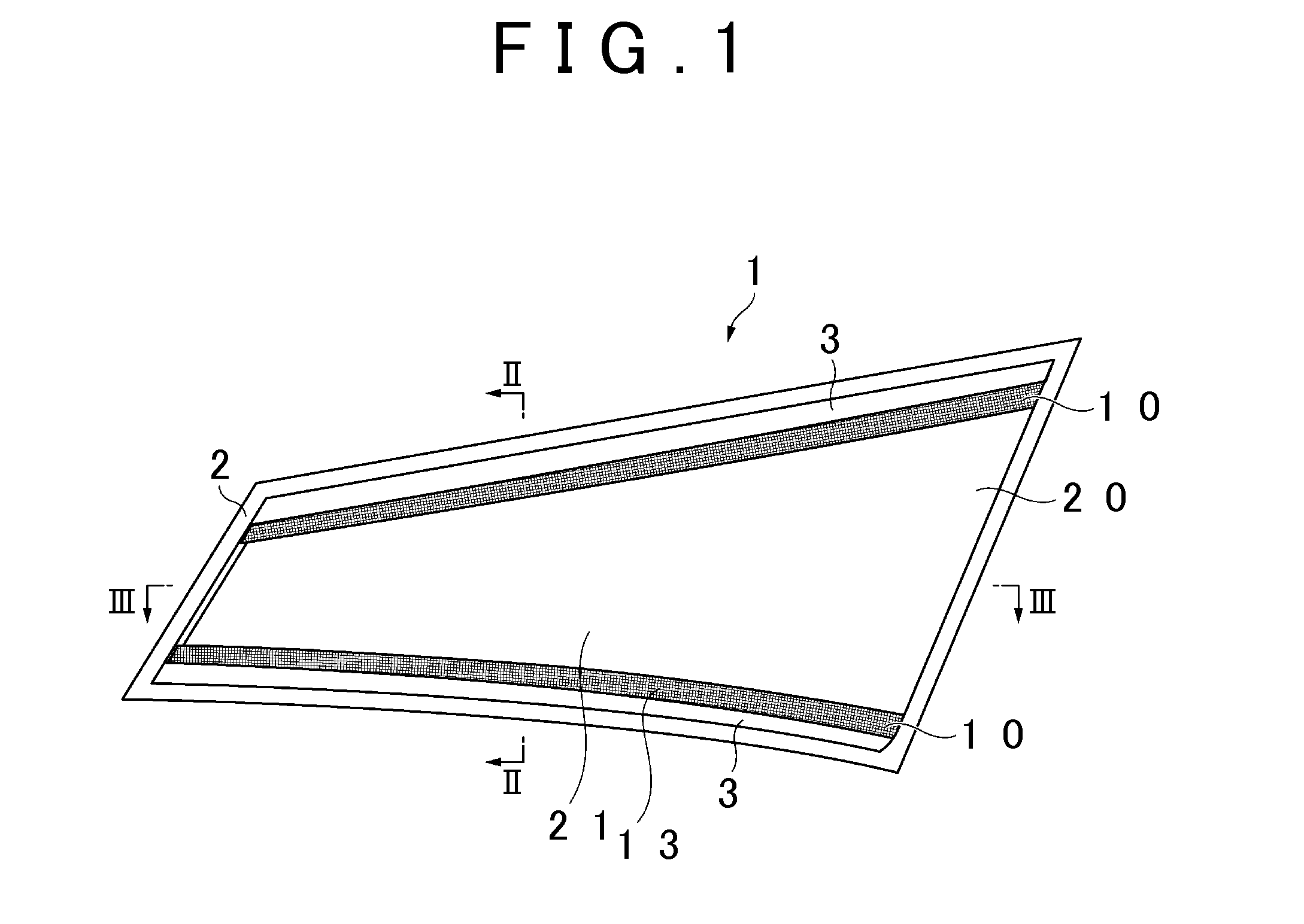
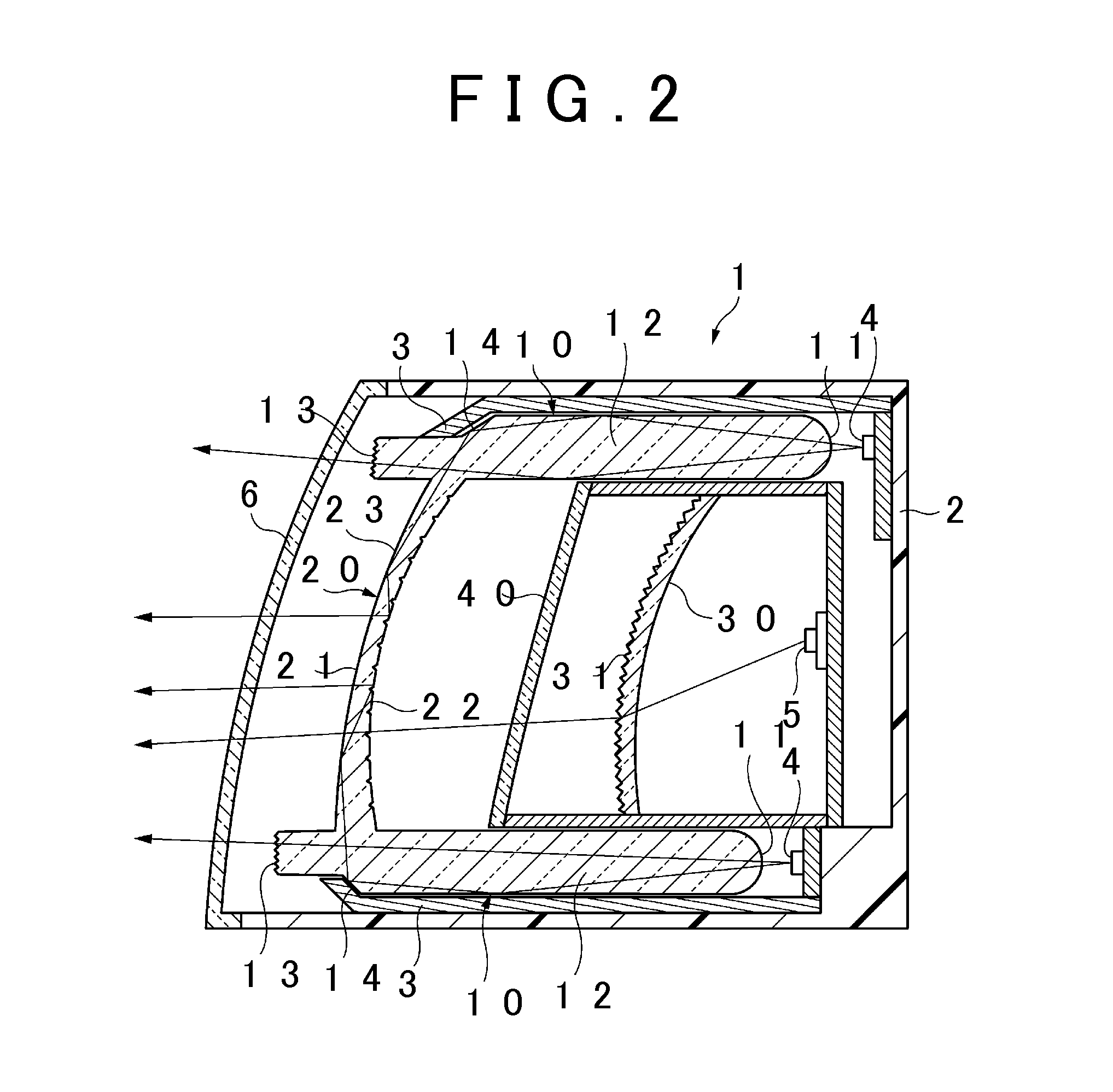
[0022]FIG. 1 is a front view of the vehicular lamp 1 according to this example embodiment. The vehicular lamp 1 shown in the drawing is a rear combination lamp provided on the right side of a vehicle rear portion. As shown in FIG. 1, the vehicular lamp 1 is a generally rectangular lamp that is long in a right-left direction (or a lateral direction) in a front view. The vehicular lamp 1 includes a transparent outer cover 6 (see FIG. 2), and a housing 2 which, together with the outer cover 6, forms a rectangular internal space. Two first light guides 10, a second light guide 20, and two extensions 3 are provided in this internal space.

[0023]The two first light guides 10 are both members that are long in the right-left direction. One of the first light guides 10 is arranged in an upper portion of the internal space (herei...

Example

Second Example Embodiment

[0045]FIG. 5 is a front view of a vehicular lamp 1A according to a second example embodiment of the invention. As shown in FIG. 5, a first light guide 10A is formed by a portion that is shaped like the letter “U” rotated 90° in the clockwise direction, which includes two portions (i.e., an upper portion and a lower portion) that extend in the lateral direction, and a portion that connects these two portions together at an end portion in the lateral direction, in a front view. A second light guide 20A is a member formed spreading out to the outside from the first light guide 10A, in a front view.

[0046]FIG. 6 is a sectional view taken along line VI-VI of FIG. 5. As shown in FIG. 6, a bar-shaped light guide 60 is provided rearward of the first light guide 10A. This bar-shaped light guide 60 is a long member that extends along a rear end surface of the first light guide 10A.

[0047]A first LED 4 is arranged on an end of the bar-shaped light guide 60 in the lengthw...

Example

Third Example Embodiment

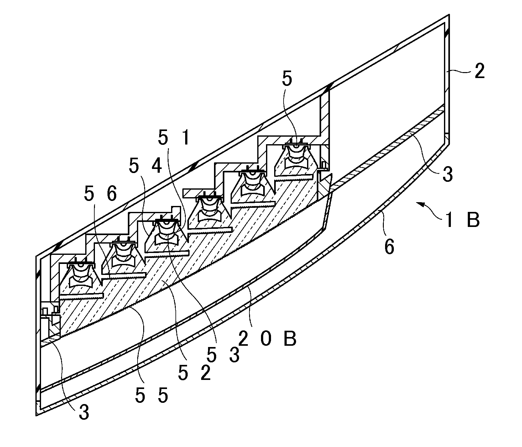
[0058]FIG. 8 is a front view of a vehicular lamp 1B according to a third example embodiment of the invention. As shown in FIG. 8, first light guides 10B are arranged in an upper portion and a lower portion of the lamp. The right end portion of the upper first light guide 10B is curved upward. The right end portion of the lower first light guide 10B is curved downward. A second light guide 20B is arranged between the upper first light guide 10B and the lower first light guide 10B. A third lens member 50 that extends in the lateral direction is provided to the rear of the second light guide 20B.

[0059]FIG. 9 is a sectional view taken along line IX-IX in FIG. 8. In the cross-section shown in FIG. 9, the first light guides 10B extend in the front-back direction. Each of the first light guides 10B has a first incident surface 11, a first light guiding portion 12, a first light emission surface 13, and a first reflecting surface 14.

[0060]The first incident surface 1...


PUM


Abstract

A vehicular lamp includes a light emitter, a first light guide, and a second light guide. The first light guide has a first incident surface, a first light guiding portion that guides the entering light, a first light emission surface that emits light guided by the first light guiding portion, and a first reflecting surface that reflects the light guided by the first light guiding portion in a direction toward the second light guide. The second light guide has a second light emission surface that emits light that enters the second light guide after being reflected by the first reflecting surface, and a second reflecting surface that reflects the light that enters the second light guide after being reflected by the first reflecting surface toward the second light emission surface.

Description

[0001]INCORPORATION BY REFERENCE[0002]The disclosure of Japanese Patent Application No. 2014-066184 filed on Mar. 27, 2014 including the specification, drawings and abstract is incorporated herein by reference in its entirety.BACKGROUND OF THE INVENTION[0003]1. Field of the Invention[0004]The invention relates to a vehicular lamp.[0005]2. Description of Related Art[0006]Japanese Patent Application Publication No. 2013-26008 (JP 2013-26008 A), for example, describes a vehicular lamp that includes a light guiding plate that extends in a horizontal direction, and a light source provided to the rear of this light guiding plate. This vehicular lamp has an excellent design because the light guiding plate emits light in a line shape when viewed from the front.SUMMARY OF THE INVENTION[0007]The vehicular lamp described in JP 2013-26008 A emits light in a line shape, so the light emitting area is small, and consequently, the visibility may be not good. Therefore, the invention provides a vehi...

Claims


Application Information

Patent Timeline
IPC IPC(8): F21V8/00F21S8/10
CPCG02B6/0076F21S48/234F21W2101/14F21Y2101/02F21S48/215B60Q1/2607B60Q1/0058F21S43/14F21S43/237F21S43/239F21S43/241F21S43/243F21S43/249F21S43/247F21S43/251F21S43/315F21S43/40F21S41/50
Inventor KOIZUMI, HIROYAMOTOMURA, KENICHITERANISHI, YASUOTAKEDA, HAJIME
Owner KOITO MFG CO LTD
Why Eureka
Try Eureka