Foldable electronic display

a technology of electronic display and foldable, which is applied in the direction of identification means, instruments, and details of portable computers, etc., can solve the problems of user's inability to at least directly see any part of the mechanism, and the flexibility of display devices is currently exploited in consumer electronics devices only to a limited extent, so as to reduce the flexing of electronics

Inactive Publication Date: 2015-10-01
FLEXENABLE LTD
View PDF4 Cites 89 Cited by
  • Summary
  • Abstract
  • Description
  • Claims
  • Application Information

AI Technical Summary

Benefits of technology

[0007]The curvature and extension of the pixel array in an embodiment may allow the user to be presented with a substantially (e.g., fully) uniform display area between an outer edge of each pixel array and the viewing side of the spine region between the panels. Substantially no physical boundary between the pixel array and an adjacent border area of the display panel at the spine side of the display panel may be visible, and / or in an area visible to, the user during rotation and / or display viewing; preferably this applies to one, some or all display panels in an embodiment. During opening and / or closing of the display, the user may thus observe merely a relative rotation of preferably rounded and touching / closely spaced display surfaces at the interface between the panels, similarly to the experience of opening / closing a book. Advantageously, the user may be unable to at least directly see any part of a mechanism for closing / opening the display, while he is facing in a direction to see the viewing sides if the display was flat open.
[0021]In a preferred embodiment, the or each display panel is preferably flexible and / or comprises an electrophoretic display screen, an electro-wetting display screen or electrofluidic display screen. Such flexibility is advantageous where a pixel array is to be bent or curved, e.g., around an edge of a panel facing the spine, to hide non-driven pixels from a user viewing an active area of the array. These displays are reflective display mediums. Electrofluidic displays enable improved brightness / contrast as well as high resolution screens and near video display update rates. Where an electrofluidic display is employed, for example of the type available from Gamma Dynamics, Inc. Ohio USA, the colour filter array may be omitted. The use of an electrofluidic display facilitates improved brightness / contrast as well as near video display update rates and high resolution, in embodiments of order 225 pixels per inch. Electrophoretic displays are an example of reflective display mediums, which allow the display device to be used in bright light conditions, such as outdoors. A colour display may be provided by providing a colour filter array over the electrophoretic display medium.
[0032]The display panel may be provided with one or more substantially rigid (preferably elongate) components, e.g. bars and / or strips, preferably along an outside edge(s) of the electronics; such components may advantageously attached, e.g., part of, the flexible support, and / or attached to the electronics, e.g., PCB. Preferably the component(s) provides some protection to the electronics and / or some support to reduce flexing of the electronics. Regardless, the component(s) may be shaped to fit against a protective cover when the structural component is attached to the display panel concerned, preferably such that discrete electronic components are fully enclosed, e.g., by the protective cover, substantially rigid components and / or a said PCB or additional cover behind the electronics.

Problems solved by technology

Display flexibility is currently exploited in consumer electronics devices only to a limited extent.
More specifically, there remain challenges in providing a display device that has any one or more of, inter alia, the following features: (a) components that should not flex are held rigid, e.g., for robustness during use; (b) the display is flexible, e.g., similar to a sheet of paper; and / or (c) the display is thin and / or light, e.g. may be held and / or carried by the user with ease and / or convenience.
Advantageously, the user may be unable to at least directly see any part of a mechanism for closing / opening the display, while he is facing in a direction to see the viewing sides if the display was flat open.
However, in an embodiment the support may have a frame shape, e.g., substantially following the periphery of the display panel and / or having a hole in the middle such that the screen is not directly supported across its entire extent.

Method used


Image

  • Foldable electronic display
  • Foldable electronic display
  • Foldable electronic display

Examples


first embodiment

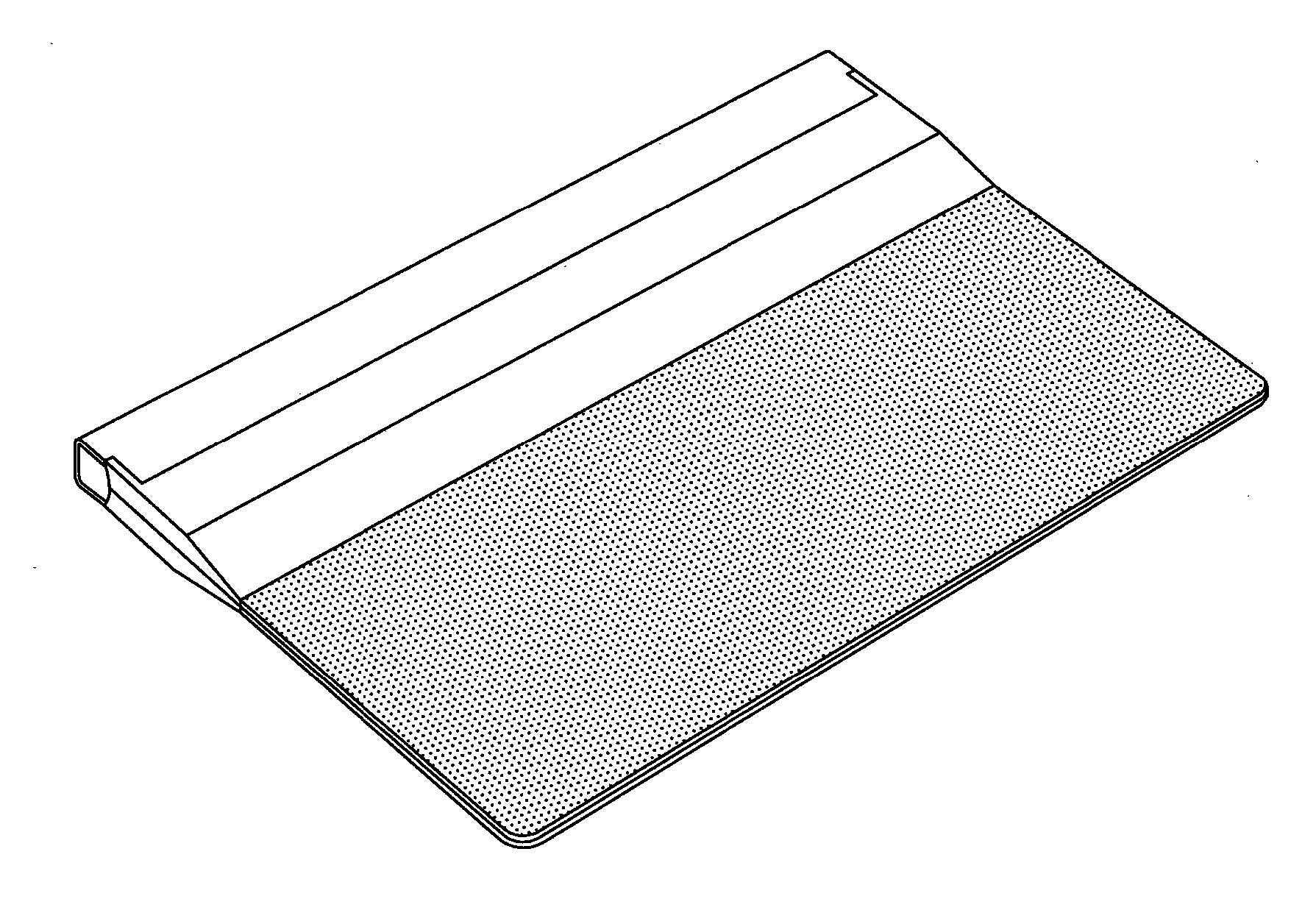
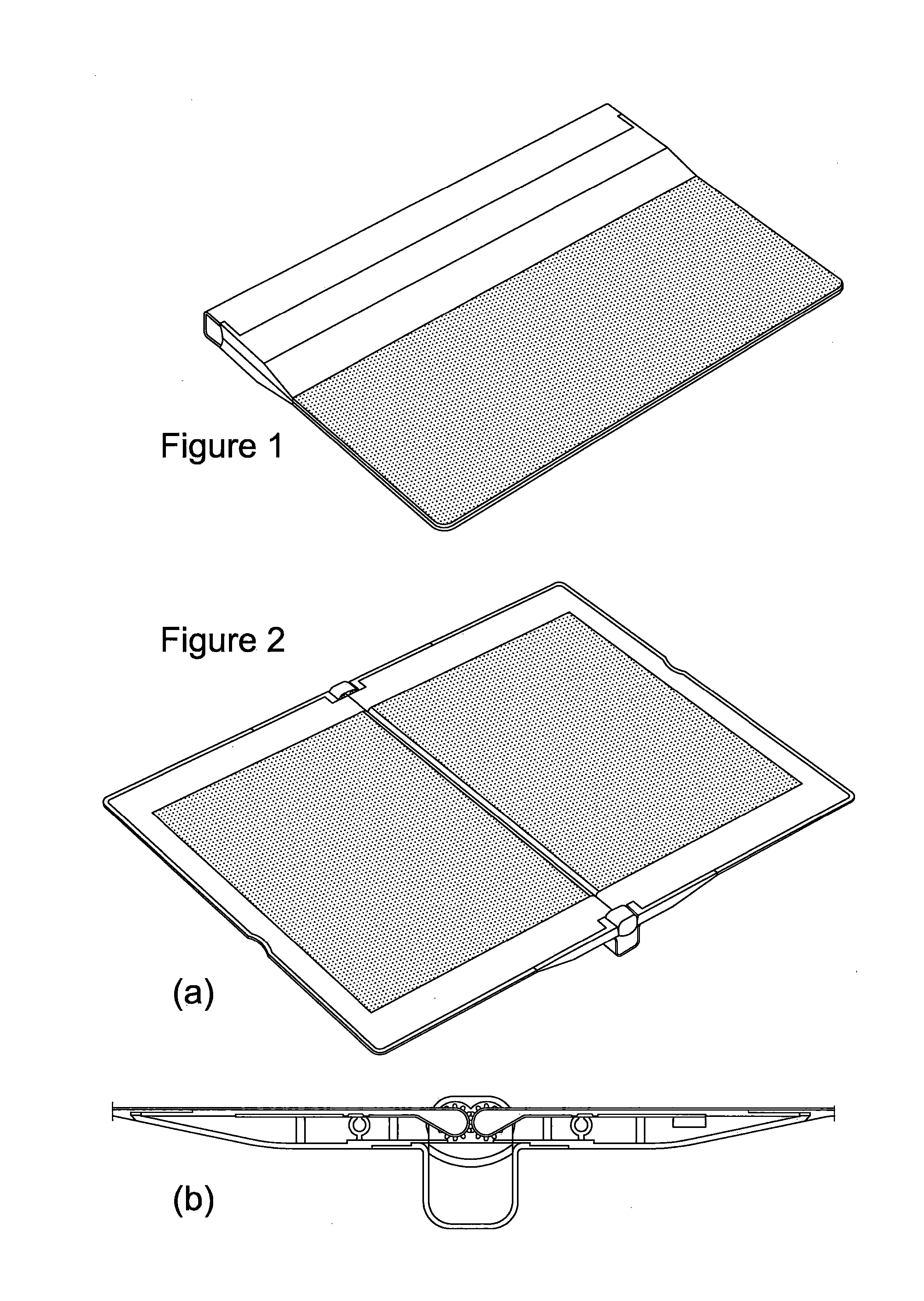
[0127]Referring to FIG. 9, this shows an electronic reading device 100 comprising a display part 102 and a handle 104 located at one edge of the display. New display part 102 is flexible and self-supporting when held by the handle, but the device lacks an internal stiffening frame and instead relies upon the structure of the device itself to provide sufficient support. This is facilitated by the device being very thin, in embodiments less than 3 mm thick, and very light, in embodiments less than 200 grams (facilitated by the device being constructed mainly of plastic, including at least some of the functional electronic components of the device). In embodiments the device is sealed and waterproof and has no physical external connections (power and communications are both exclusively wireless).

[0128]In embodiments the device has no separate housing or enclosure; instead the device or at least substantially the entirety of the display part of the device has a continuous, unitary struc...

second embodiment

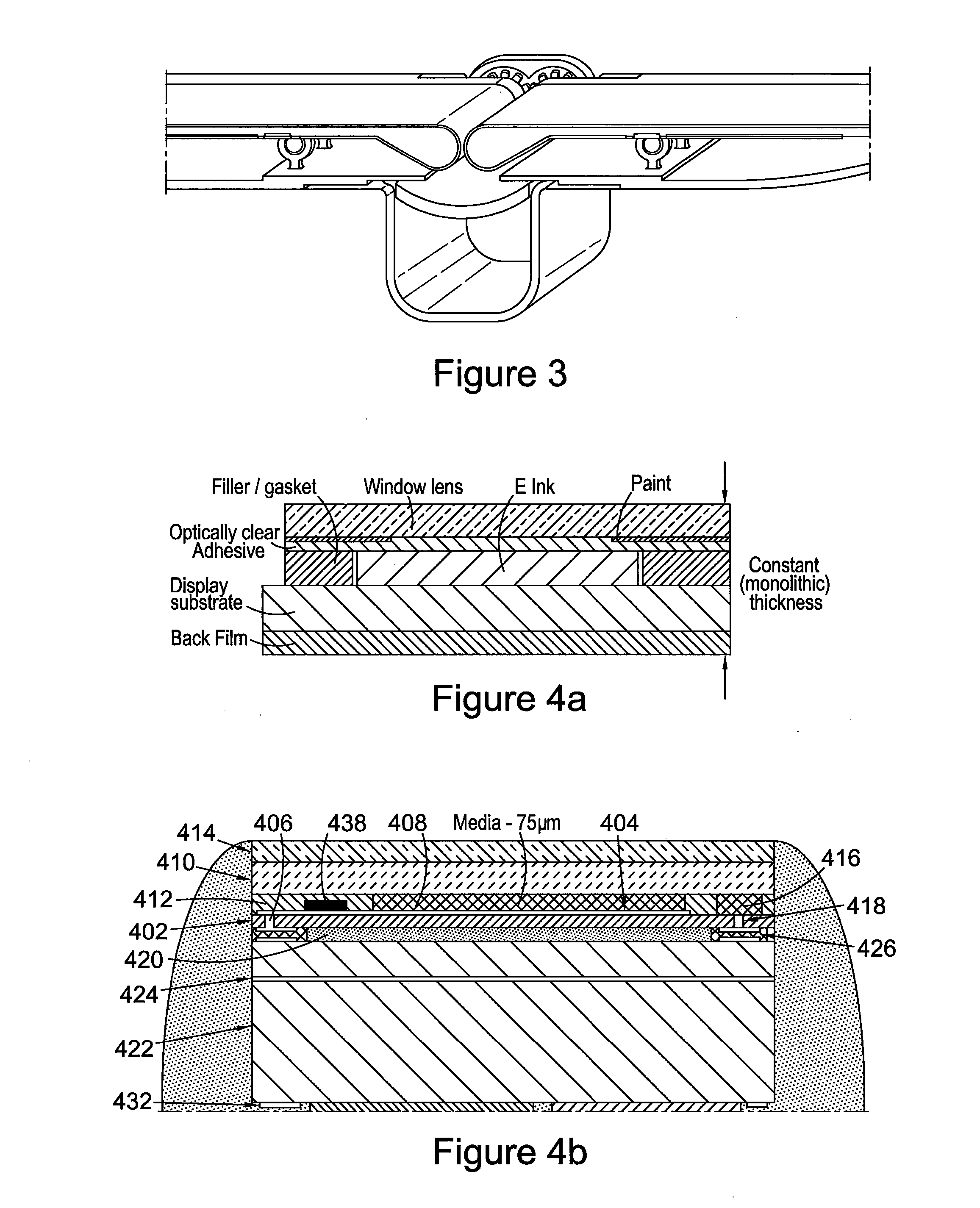
[0134]Referring now to FIG. 12, this shows a vertical cross-section view through an electronic reading device 400 in which electronic components of the device are distributed over a surface of the device on a flexible PCB. Nonetheless a display stack of the type illustrated in FIG. 12 may also be employed for the embodiment of FIG. 9.

[0135]In more detail, the structure comprises a substrate 402, typically a plastic such as PET (polyethyleneterephthalate) or pen(polyethelenemaphthalene) on which is fabricated a thin layer of organic active matrix pixel circuitry. The circuitry may comprise an array of organic (or inorganic) thin film transistors for example as previously described in our WO01 / 47045, WO2004 / 070466, WO01 / 47043, WO2006 / 059162, WO2006 / 056808, WO2006 / 061658, WO2006 / 106365 and WO2007 / 029028. Broadly speaking in embodiments the backplane is fabricated using solution based techniques patterned by, for example, direct-right printing, laser ablation or photolithography to fabr...


PUM


Abstract

A foldable electronic display comprising first and second display panels. Each said display panel has opposed viewing and back sides and a curved edge between said viewing and back sides. Each display panel further comprises an array of pixels comprising display medium an electronics to control said array of pixels to display an image on said viewing side. The display comprises coupling means configured to retain a said edge of said first display panel adjacent to and substantially aligned to a said edge of said second display panel. The pixel array of at least said first display panel is curved to extend from said front, viewing side of the display panel at least to a region of said curved edge of the display panel. The coupling means is configured to allow rotation of a said display panel to roll the curved edge of a said first or second display panel over the adjacent edge of the other of the first and second display panels to open the display such that a boundary of the pixel array extension is not in an area visible to the user during said opening, said boundary in said region of said curved edge or back side of said first display panel.

Description

FIELD OF THE INVENTION[0001]The present invention generally relates to a foldable electronic display, a method of unfolding an electronic display comprising a plurality of display panels, and more particularly to an electronic book and to an e-reader.BACKGROUND TO THE INVENTION[0002]Display flexibility is currently exploited in consumer electronics devices only to a limited extent. One reason for this may be the challenge of integrating flexible displays into products, such that the benefits of the display flexibility may be fully exploited yet the product remains robust enough to be handled by consumers. More specifically, there remain challenges in providing a display device that has any one or more of, inter alia, the following features: (a) components that should not flex are held rigid, e.g., for robustness during use; (b) the display is flexible, e.g., similar to a sheet of paper; and / or (c) the display is thin and / or light, e.g. may be held and / or carried by the user with eas...

Claims


Application Information

Patent Timeline
Patent Type & Authority Applications(United States)
IPC IPC(8): G06F1/16G06F3/14G09F9/30
CPCG06F1/1641G06F3/1438G09F9/301G06F1/1652G06F1/1616
Inventor REEVES, WILLIAMHUTCHINSON, PETER
Owner FLEXENABLE LTD
Why Eureka
Try Eureka