
Method and apparatus for implementing a dynamic out-of-order processor pipeline

a technology of dynamic out-of-order processors and pipelines, applied in the field of apparatus and methods for implementing dynamic out-of-order processor pipelines, can solve the problems of increasing hardware scalability, power efficiency, area density, and increasing difficulty in improving the performance of these processors

Inactive Publication Date: 2015-10-01
INTEL CORP
View PDF8 Cites 17 Cited by
  • Summary
  • Abstract
  • Description
  • Claims
  • Application Information

AI Technical Summary

Benefits of technology

The patent describes an invention that relates to computer processors and how to improve their performance. The invention proposes a dynamic out-of-order processor pipeline that can be implemented in a variety of processor architectures. The invention aims to improve the performance of processors by optimizing the performance of out-of-order processors, which are becoming more important in mainstream processor designs. The invention provides a solution for addressing the challenges of out-of-order processing, such as power efficiency and area density, and helps to improve the performance of processors with integrated memory controllers and graphics. The invention also includes a system on a chip (SoC) that incorporates a processor pipeline and a method for register renaming, out-of-order issue / execution, and cancellation logic. Overall, the invention provides a way to improve the performance of processors by optimizing out-of-order processing and addressing the challenges of out-of-order processing.

Problems solved by technology

Improving the performance of these processors, power efficiency, area density, and hardware scalability becomes increasingly more difficult with each generation of the hardware-only out of order designs.

Method used


Image

  • Method and apparatus for implementing a dynamic out-of-order processor pipeline
  • Method and apparatus for implementing a dynamic out-of-order processor pipeline
  • Method and apparatus for implementing a dynamic out-of-order processor pipeline

Examples


Embodiment Construction

[0024]In the following description, for the purposes of explanation, numerous specific details are set forth in order to provide a thorough understanding of the embodiments of the invention described below. It will be apparent, however, to one skilled in the art that the embodiments of the invention may be practiced without some of these specific details. In other instances, well-known structures and devices are shown in block diagram form to avoid obscuring the underlying principles of the embodiments of the invention.

Exemplary Processor Architectures and Data Types

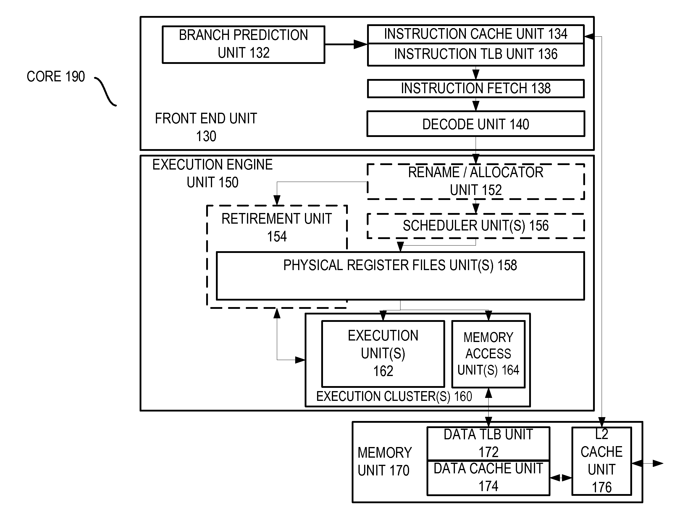
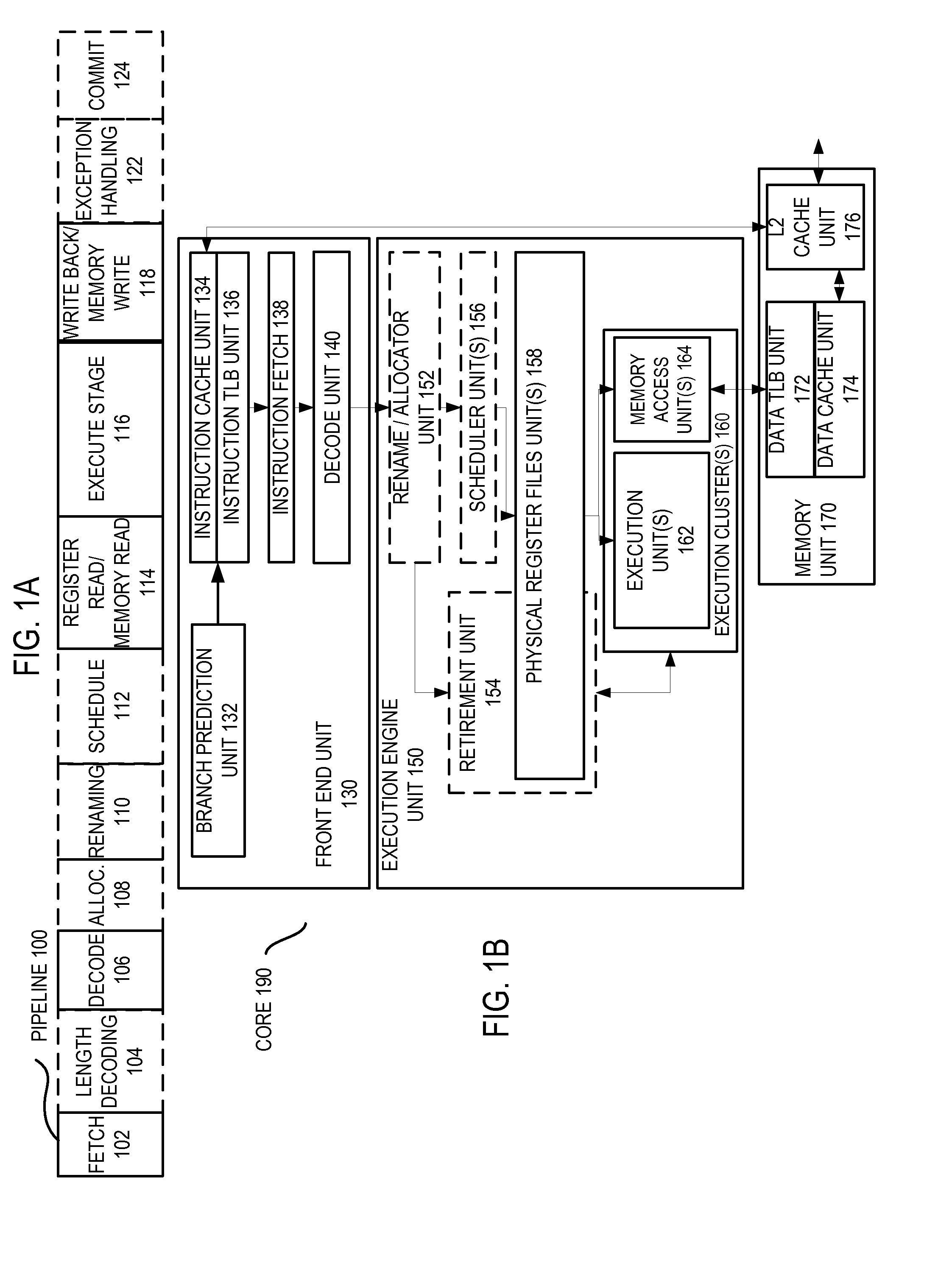
[0025]FIG. 1A is a block diagram illustrating both an exemplary in-order pipeline and an exemplary register renaming, out-of-order issue / execution pipeline according to embodiments of the invention. FIG. 1B is a block diagram illustrating both an exemplary embodiment of an in-order architecture core and an exemplary register renaming, out-of-order issue / execution architecture core to be included in a processor according ...


PUM


Abstract

A hardware / software co-design for an optimized dynamic out-of-order Very Long Instruction Word (VLIW) pipeline. For example, one embodiment of an apparatus comprises: an instruction fetch unit to fetch Very Long Instruction Words (VLIWs) in their program order from memory, each of the VLIWs comprising a plurality of reduced instruction set computing (RISC) instruction syllables grouped into the VLIWs in an order which removes data-flow dependencies and false output dependencies between the syllables; a decode unit to decode the VLIWs in their program order and output the syllables of each decoded VLIW in parallel; and an out-of-order execution engine to execute the syllables preferably in parallel with other syllables, wherein at least some of the syllables are to be executed in a different order than the order in which they are received from the decode unit, the out-of-order execution engine having one or more processing stages which do not check for data-flow dependencies and false output dependencies between the syllables when performing operations.

Description

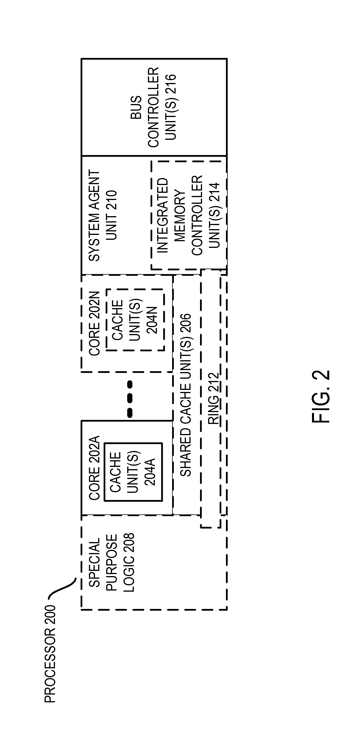
BACKGROUND[0001]1. Field of the Invention[0002]This invention relates generally to the field of computer processors. More particularly, the invention relates to an apparatus and method for implementing a dynamic out-of-order processor pipeline.[0003]2. Description of the Related Art[0004]Many mainstream processors are currently based on dynamic out-of-order microarchitectures, which share more or less same high-level principles of out-of-order pipeline implementation. Improving the performance of these processors, power efficiency, area density, and hardware scalability becomes increasingly more difficult with each generation of the hardware-only out of order designs.BRIEF DESCRIPTION OF THE DRAWINGS[0005]A better understanding of the present invention can be obtained from the following detailed description in conjunction with the following drawings, in which:[0006]FIG. 1A is a block diagram illustrating both an exemplary in-order pipeline and an exemplary register renaming, out-of-...

Claims


Application Information

Patent Timeline
IPC IPC(8): G06F9/38G06F9/30
CPCG06F9/30145G06F9/3802G06F9/3836G06F9/3853G06F9/3891G06F9/30149G06F9/30152G06F9/3856G06F9/3885G06F9/3004G06F9/30196G06F9/3867G06F9/46
Inventor KHARTIKOV, DENIS M.NEELAKANTAM, NAVEENKELM, JOHN H.XEKALAKIS, POLYCHRONIS
Owner INTEL CORP
Learn More