
Pixel unit of organic electroluminescent display

a technology of electroluminescent display and pixel unit, which is applied in the field of pixel unit, can solve problems such as background image blues, and achieve the effect of preferable transparent display

Active Publication Date: 2015-10-01
OPTRONIC SCI LLC
View PDF2 Cites 17 Cited by
  • Summary
  • Abstract
  • Description
  • Claims
  • Application Information

AI Technical Summary

Benefits of technology

This invention relates to an organic electroluminescent display with a pixel unit that provides a better transparent display effect. The power line and data line are distributed inside the transparent area for each pixel unit, which reduces the impact on background images due to concentrated data and power positions. This helps to improve the overall blur issue for the display.

Problems solved by technology

The background image light beam is non-uniformly blocked by the mesh region while passing through the organic electroluminescent display, which then leads to a blur issue for the background image.
In addition, the conventional power line is mostly a mesh structure composed of vertical lines and horizontal lines, and the mesh structure can easily be interfered with a background object having a periodic structure to generate the Moire fringes that is disadvantageous for a transparent display effect.

Method used


Image

  • Pixel unit of organic electroluminescent display
  • Pixel unit of organic electroluminescent display
  • Pixel unit of organic electroluminescent display

Examples


Embodiment Construction

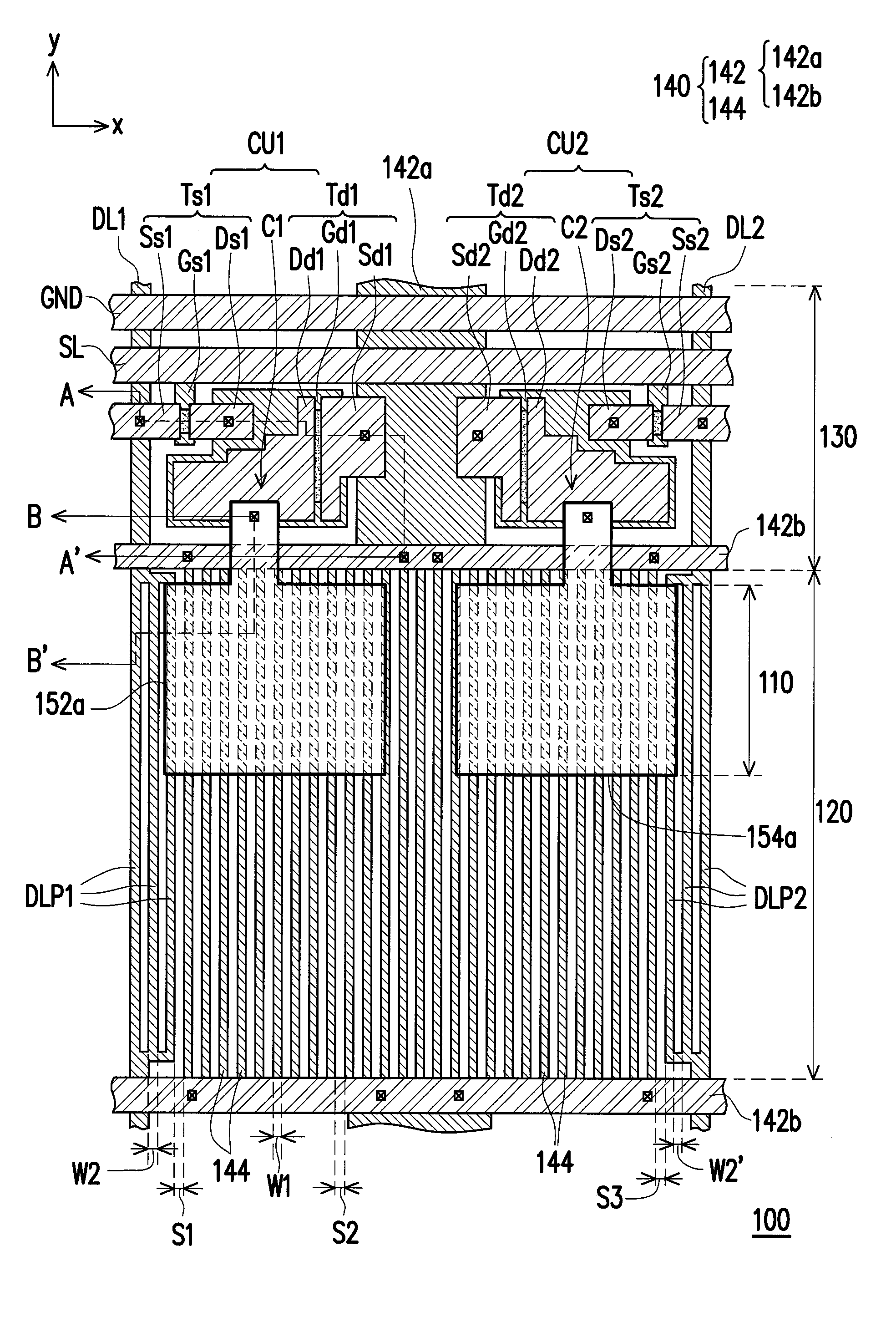
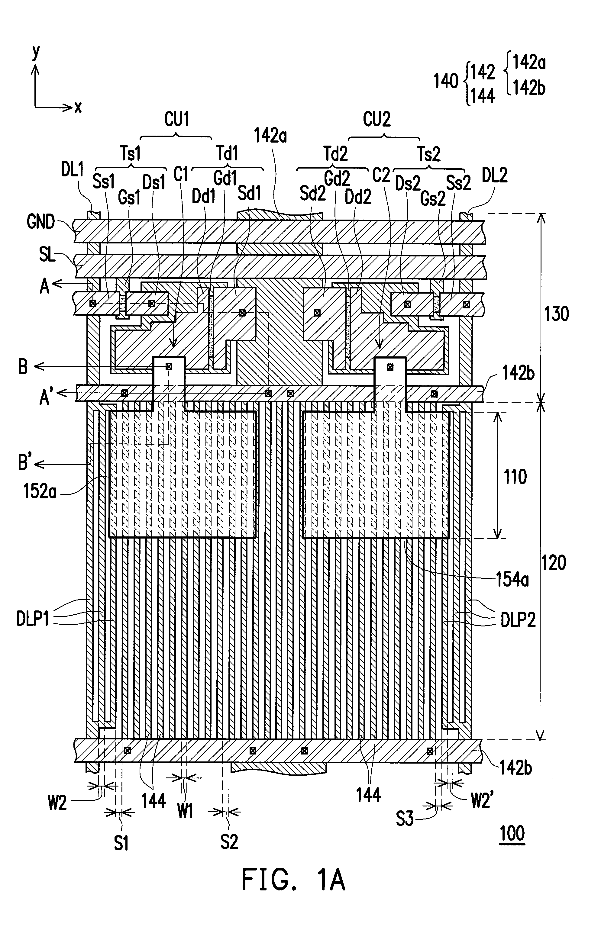
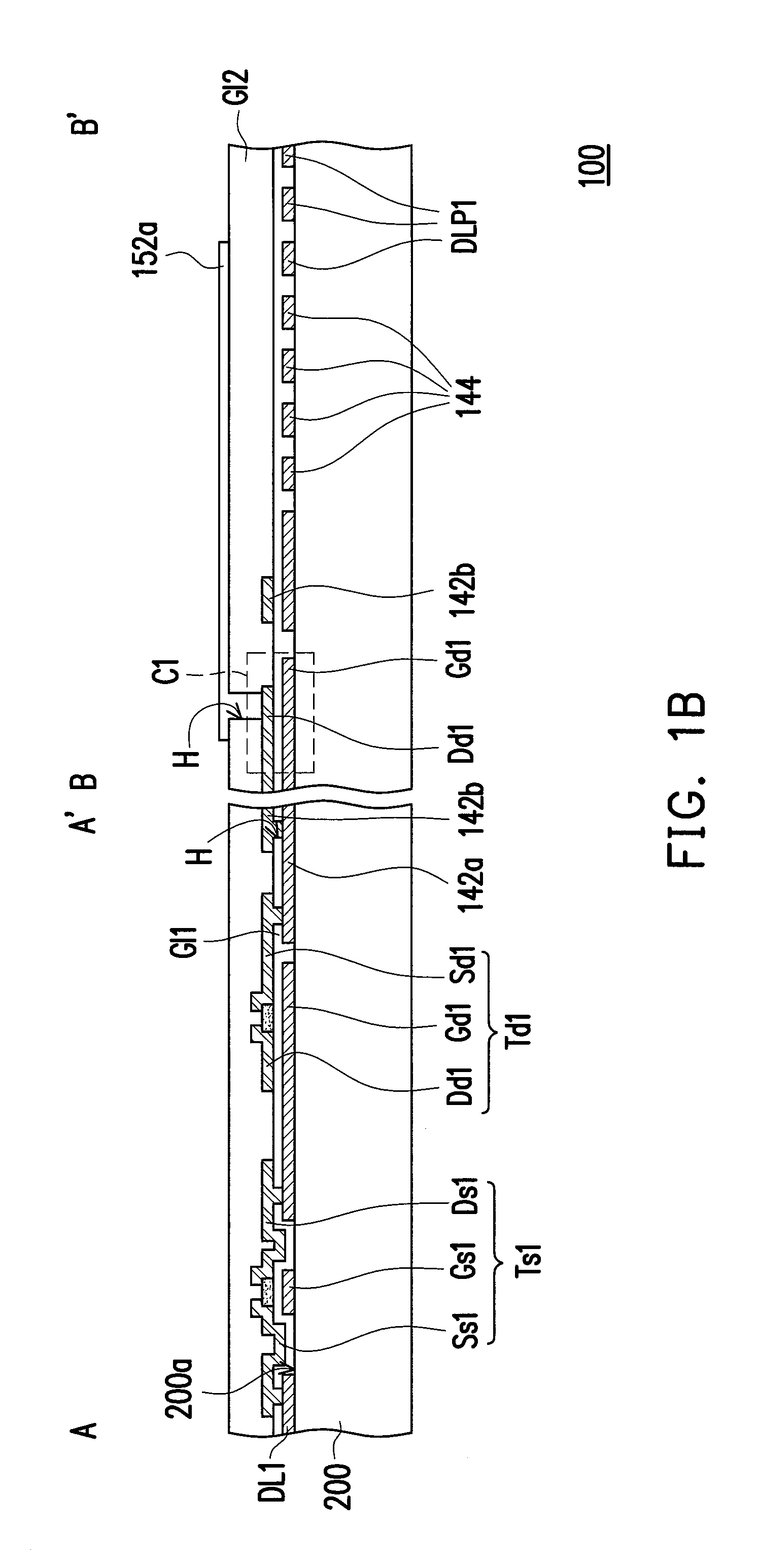
[0024]FIG. 1A is a top view of a pixel unit of an organic electroluminescent display according to an embodiment of the invention. FIG. 1B is a cross-sectional view of the pixel unit of the organic electroluminescent display of FIG. 1A along section-lines A-A′ and B-B′. Referring to FIG. 1A and FIG. 1B, a pixel unit 100 has a light emitting area 110 and a transparent area 120. The pixel unit 100 further includes a control element area 130 outside the transparent area 120. The pixel unit 100 at least includes a scan line SL, a first data line DL1, a first control element CUL a power line 140 and an electrode 152a of a first organic light-emitting diode. In the present embodiment, the pixel unit 100 may further include a second data line DL2, a second control element CU2 and an electrode 154a of a second organic light-emitting diode. It should be noted that, amounts of the data lines, the control elements and electrodes of the organic light-emitting diodes included in the pixel unit of...


PUM


Abstract

A pixel unit of an organic electroluminescent display having a light emitting area and a transparent area is provided. The pixel unit includes a scan line, a data line, a control element electrically connected to the scan line and the data line, a power line electrically connected to the control element and an organic light-emitting diode disposed inside the light emitting area and electrically connected to the power line and the control element. The power line includes a main portion and a plurality of branch portions connected to the main portion. The branch portions are disposed inside the transparent area and electrically independent from the data line. A width of each of the branch portions is identical to a minimum line width of the data line.

Description

CROSS-REFERENCE TO RELATED APPLICATION[0001]This application claims the priority benefit of Taiwan application serial no. 103111948, filed on Mar. 31, 2014. The entirety of the above-mentioned patent application is hereby incorporated by reference herein and made a part of this specification.BACKGROUND OF THE INVENTION[0002]1. Field of the Invention[0003]The invention relates to a pixel unit, and more particularly, relates to a pixel unit of an organic electroluminescent display.[0004]2. Description of Related Art[0005]With advancement in display technologies, transparent displays have been gradually developed. A transparent display has a sufficient transparency rate, which enables a person to clearly watch a background image behind the transparent display. Since the transparent display may be applied to windows of buildings or cars, or may be used in showcase events, the transparent display has attracted great attention of the market. Generally, the transparent display may be class...

Claims


Application Information

Patent Timeline
Patent Type & Authority Applications(United States)
IPC IPC(8): G09G3/32
CPCG09G3/3233G09G3/3258G09G2300/0819G09G2310/0262G09G2300/0852G09G2320/045G09G2310/0251G09G2300/0861G09G2300/0426G09G2300/0842H10K59/121H10K59/131
Inventor XI, PENG-BOHSU, YA-LING
Owner OPTRONIC SCI LLC
Learn More