
Cable and harness using the cable

a technology of cable and harness, which is applied in the direction of cables, insulated conductors, conductors, etc., can solve the problems of cable appearance deterioration, cracks derived from wrinkles, and wrinkles on the surface of the sheath layer, so as to reduce the likelihood of deterioration in appearance and less likely to be broken

Inactive Publication Date: 2015-10-01
HITACHI METALS LTD
View PDF7 Cites 7 Cited by
  • Summary
  • Abstract
  • Description
  • Claims
  • Application Information

AI Technical Summary

Benefits of technology

The invention provides a cable that is less likely to look bad and break, as well as a harness that uses this cable.

Problems solved by technology

The cables with the sheath layer of the medical insulating resin such as PVC may have the problem that a wrinkle occurs on a surface of the sheath layer especially by being bent at a small bend radius since the elasticity of the sheath layer is low.
Thus, the appearance of the cables may deteriorate.
They may also have the problem that a crack is derived from the wrinkle on the sheath layer by repeatedly bending a portion nearby the wrinkle.
Furthermore, they may have the problem that since the ultrasonograph probe cable is as long as 2.2 to 3 m, it is broken by being stepped on when a part thereof is fallen on the floor or it is caught by a surrounding structure etc.

Method used


Image

  • Cable and harness using the cable
  • Cable and harness using the cable
  • Cable and harness using the cable

Examples


Embodiment Construction

[0031]An embodiment of the invention will be described below in conjunction with the appended drawings.

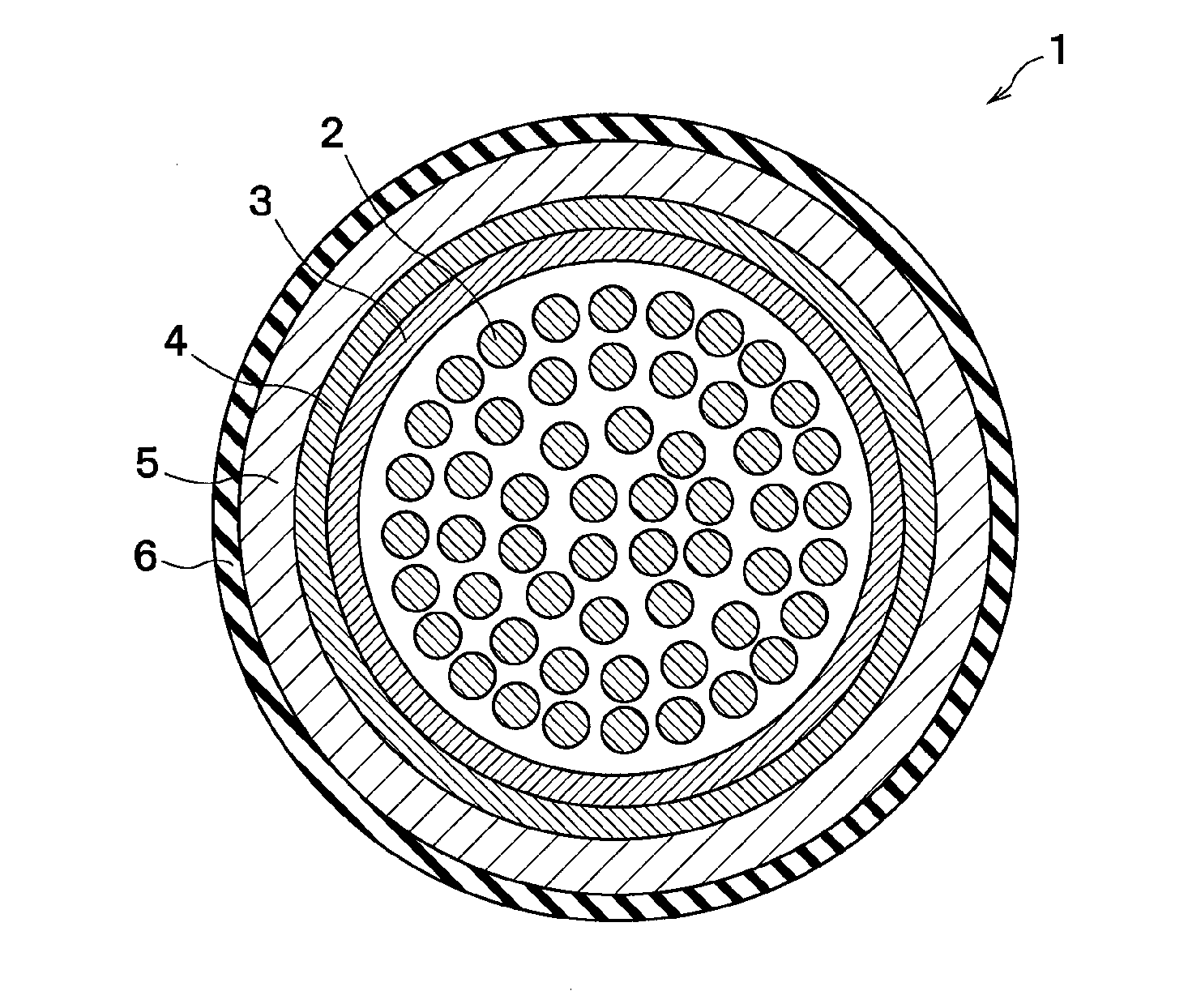
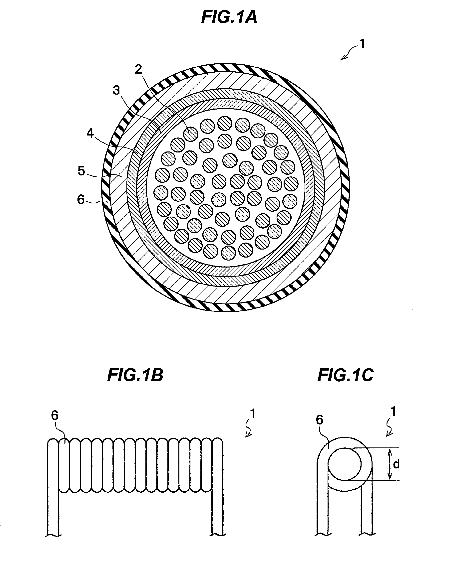
[0032]FIGS. 1A to 1C are illustration diagrams showing a cable in the present embodiment, wherein FIG. 1A is a cross sectional view, FIG. 1B is a side view and FIG. 1C is a front view.

[0033]As shown in FIG. 1A, in a cable 1, a sheath layer 6 formed of a medical insulating resin is provided as the outermost layer and a buffer layer 5 formed of a rubber elasticity resin is provided on the inner side of the sheath layer 6 so as to be tightly adhered to the sheath layer 6.

[0034]The cable 1 as a probe cable for ultrasonography will be described here.

[0035]The cable 1 is formed by covering plural (e.g., not less than one hundred) core wires 2 all together with a binding tape 3, a braided shield 4, the buffer layer 5 and the sheath layer 6 which are provided in this order on the plural core wires 2.

[0036]The core wires 2 comprise plural coaxial lines for signal transmission and plural ins...


PUM

PropertyMeasurementUnit
temperatureaaaaaaaaaa
elasticityaaaaaaaaaa
softening temperatureaaaaaaaaaa

Abstract

A cable includes sheath layer at an outermost layer, the sheath layer including a medical insulating resin, and a buffer layer closely contacting the sheath layer inside the sheath layer. The buffer layer includes a rubber elasticity resin.

Description

[0001]The present application is based on Japanese patent application No.2014-066159 filed on Mar. 27, 2014, the entire contents of which are incorporated herein by reference.BACKGROUND OF THE INVENTION[0002]1. Field of the Invention[0003]The invention relates to a cable such as a ultrasonograph probe cable used in medical applications, and a harness using the cable.[0004]2. Description of the Related Art[0005]A ultrasonograph probe cable is known that is provided with multiple core wires (coaxial lines and insulated wires), a binding tape bundling the core wires and a braided shield and a sheath layer provided in this order on the outer periphery of the binding tape.[0006]In medical-use cables such as the ultrasonograph probe cable, a sheath layer of a medical insulating resin is used as the outermost layer.[0007]The medical insulating resin is also called a medical resin or a medical grade resin. It is biocompatible (or highly biologically compatible), non-toxic and does not cause...

Claims


Application Information

Patent Timeline
Patent Type & Authority Applications(United States)
IPC IPC(8): H01B7/18H01B7/00A61L31/14H01B3/30A61L31/04A61B8/00H01B3/44
CPCH01B7/188A61B8/4444H01B7/0045A61L31/14H01B3/307A61L31/041H01B3/443H01B3/445H01B7/04H01B7/065
Inventor HUANG, DETIANWATANABE, TAKANOBUKUDO, KIMIKA
Owner HITACHI METALS LTD
Learn More