Heat dissipation device having power wires fixture

a heat dissipation device and power wire technology, applied in the direction of coupling device connections, semiconductor/solid-state device details, instruments, etc., can solve the problems of reducing the disassembly efficiency of the heat dissipation apparatus in the computer, contaminating the wires with dust and dirt, and deteriorating the appearance of the wires

Inactive Publication Date: 2007-02-08
HON HAI PRECISION IND CO LTD
View PDF7 Cites 2 Cited by
  • Summary
  • Abstract
  • Description
  • Claims
  • Application Information

AI Technical Summary

Problems solved by technology

The remained adhesive on the wires may deteriorate the appearance of the wires and contaminate the wires with dusts and dirt.
In conventional operation, the remained adhesive needs t

Method used


Image

  • Heat dissipation device having power wires fixture
  • Heat dissipation device having power wires fixture
  • Heat dissipation device having power wires fixture

Examples


Embodiment Construction

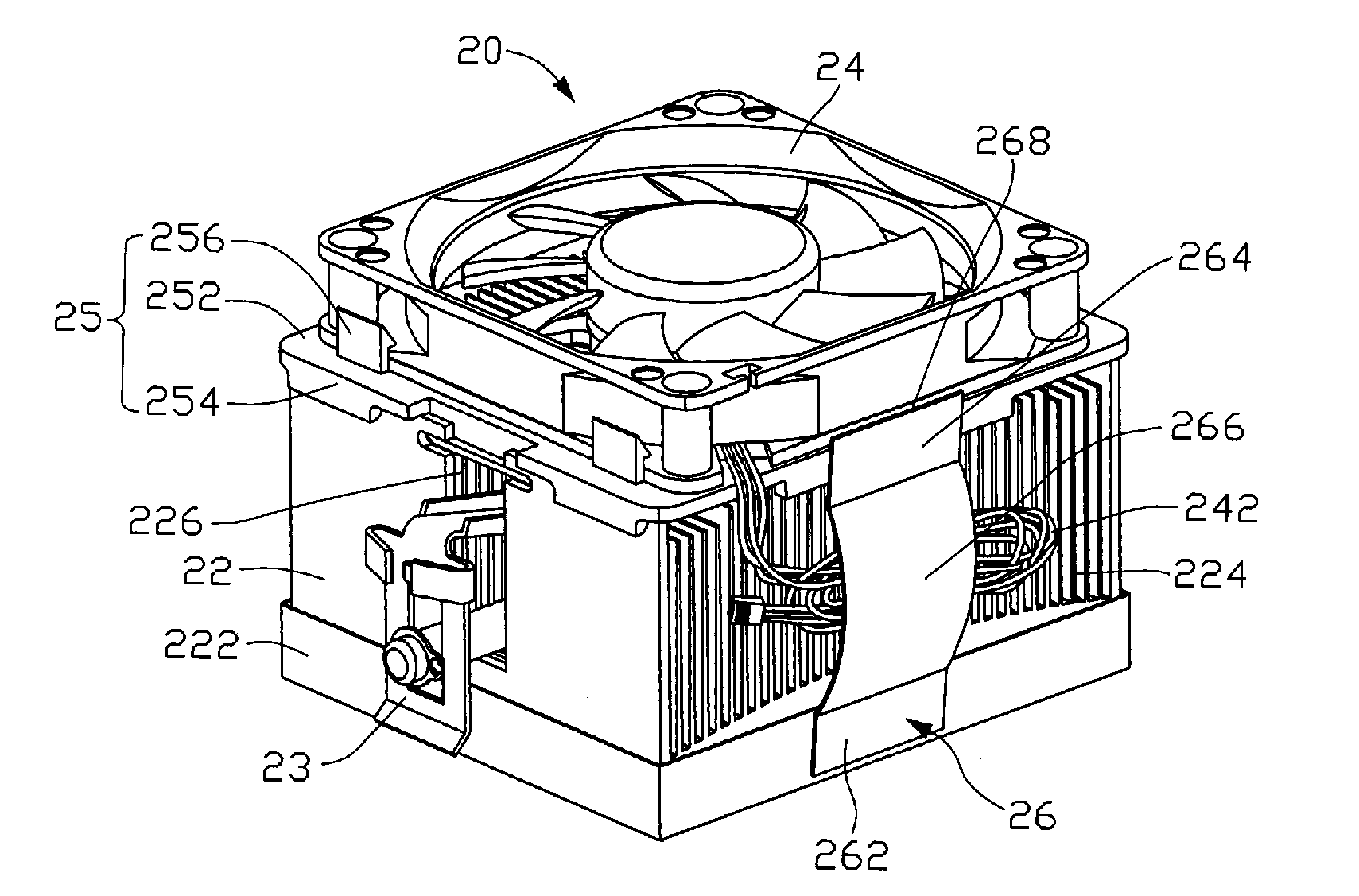
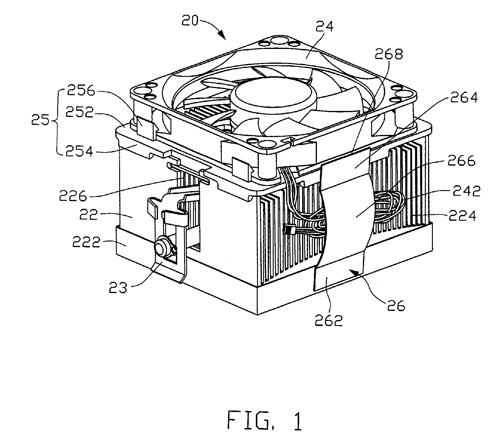
[0010] Referring to FIG. 1, a heat dissipation apparatus 20 for timely removing heat generated by a heat-generating electronic component (not shown) includes a heat sink 22 contacting with the heat-generating component, a clip 23 for mounting the heat sink 22 on the heat-generating component, a heat-dissipating fan 24 for driving airflows to pass through the heat sink 22 to take away heat therefrom, a bracket 25 for mounting the heat-dissipating fan 24 onto the heat sink 22, and a wire fixture 26 for attaching power wires 242 of the heat-dissipating fan 24 to the heat dissipation apparatus 20.

[0011] The heat sink 22 includes a base 222 thermally contacting with the heat-generating component, and a plurality of fins 224 mounted on the base 222. A channel 226 is defined at a middle portion of the heat sink 22 extending through the fins 224 for receiving the clip 23 therein.

[0012] The bracket 25 is sandwiched between the heat sink 22 and the heat-dissipating fan 24. The bracket 25 in...


PUM


Abstract

A wire fixture (26) for fastening power wires (242) of a heat-dissipating fan (24) to a supporting surface of a heat dissipation apparatus (20). The wire fixture includes a first engaging end (262), a second engaging end (264), and a covering portion (266). The first and second engaging ends are provided with adhesive (27) thereon for being attached to the supporting surface. The covering portion is formed between the first and second engaging ends and without adhesive thereon, for sandwiching the wires of the heat dissipating fan between the wire fixture and the supporting surface of the heat dissipation apparatus.

Description

FIELD OF THE INVENTION [0001] The present invention relates generally to a heat dissipation device, and particularly to a heat dissipation device having a fixture for attaching power wires of a heat dissipating fan of the heat dissipation device to a heat sink thereof. DESCRIPTION OF RELATED ART [0002] A heat dissipation apparatus always includes a heat dissipating fan. In transportation of the heat dissipation apparatus, power wires of the heat dissipating fan needs to be fixed to the heat dissipation apparatus, for facilitating handling of the heat dissipation apparatus during the transportation. [0003] In nowadays, the wires are usually wrapped into a coil which is fixed to the heat dissipation apparatus by a tape with adhesive coated wholly on one of two major surfaces thereof. In fixation of the wires, a middle portion of the tape is adhered to the wires. Then, the wires and the tape are positioned on the heat dissipation apparatus, with two ends of the tape being adhered to th...

Claims


Application Information

Patent Timeline
IPC IPC(8): H01R13/72
CPCG06F1/20H01L23/467H01L2924/0002H01L2924/00
Inventor YU, FANG-XIANG
Owner HON HAI PRECISION IND CO LTD
Why Eureka
Try Eureka