
Fastening device of plug-socket combination

a technology of fastening device and plug socket, which is applied in the direction of coupling device connection, two-part coupling device, electrical apparatus, etc., can solve the problems of lowering product yield rate, severe loss and damage, and loss of original processing or operation parameters, so as to improve strength and not easily detachable

Inactive Publication Date: 2015-10-01
RONG FENG INDAL
View PDF2 Cites 10 Cited by
  • Summary
  • Abstract
  • Description
  • Claims
  • Application Information

AI Technical Summary

Benefits of technology

The present invention provides a better fastening device for plug-socket combinations. It includes a fastening plate made through plastic injection with a plastic pawl integrated with it. The plastic pawl catches a large area and has improved strength. Additionally, it is difficult to detach.

Problems solved by technology

One of the most influencing events for an industrial processing machine is unexpected interruption of power supply.
The interruption of power supply may result in lowering of product yield rate and also affect the schedule of the processing operation and what is even worse is causing loss of the original processing or operation parameters.
Further, power failure or interruption of power supply may lead to severe loss and damage.
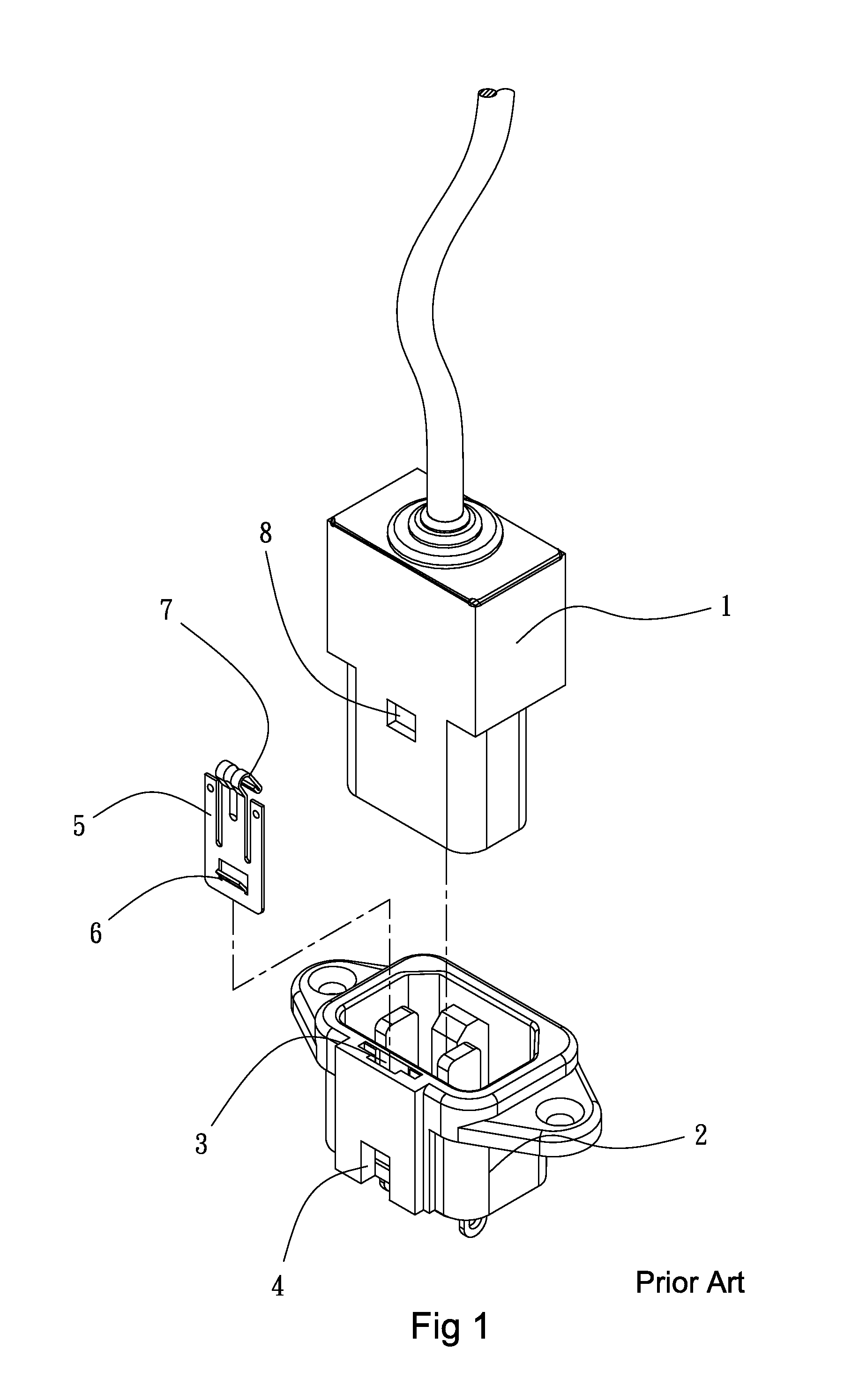
However, such a simple way of connection may cause ready separation of the blades of the plug from the slots of the socket due to for example stretching or pulling of the electrical cables to which the plug and the socket are mount or pulling of the plug and socket themselves.
The consequence of such separation is the interruption of power supply.
However, although it is possible to prevent separation caused by pulling or stretching, the fastening plate 5 is made of metal so that the fastening plate 5 and the pawl 7 have a thickness that is small, providing the elastic pawl 7 with insufficient strength.

Method used


Image

  • Fastening device of plug-socket combination
  • Fastening device of plug-socket combination
  • Fastening device of plug-socket combination

Examples


Embodiment Construction

[0017]The present invention provides an improved fastening device of a plug-socket combination. A detailed description will be given to discuss the structural features and other advantages and objects of the present invention with reference to the accompanying drawings.

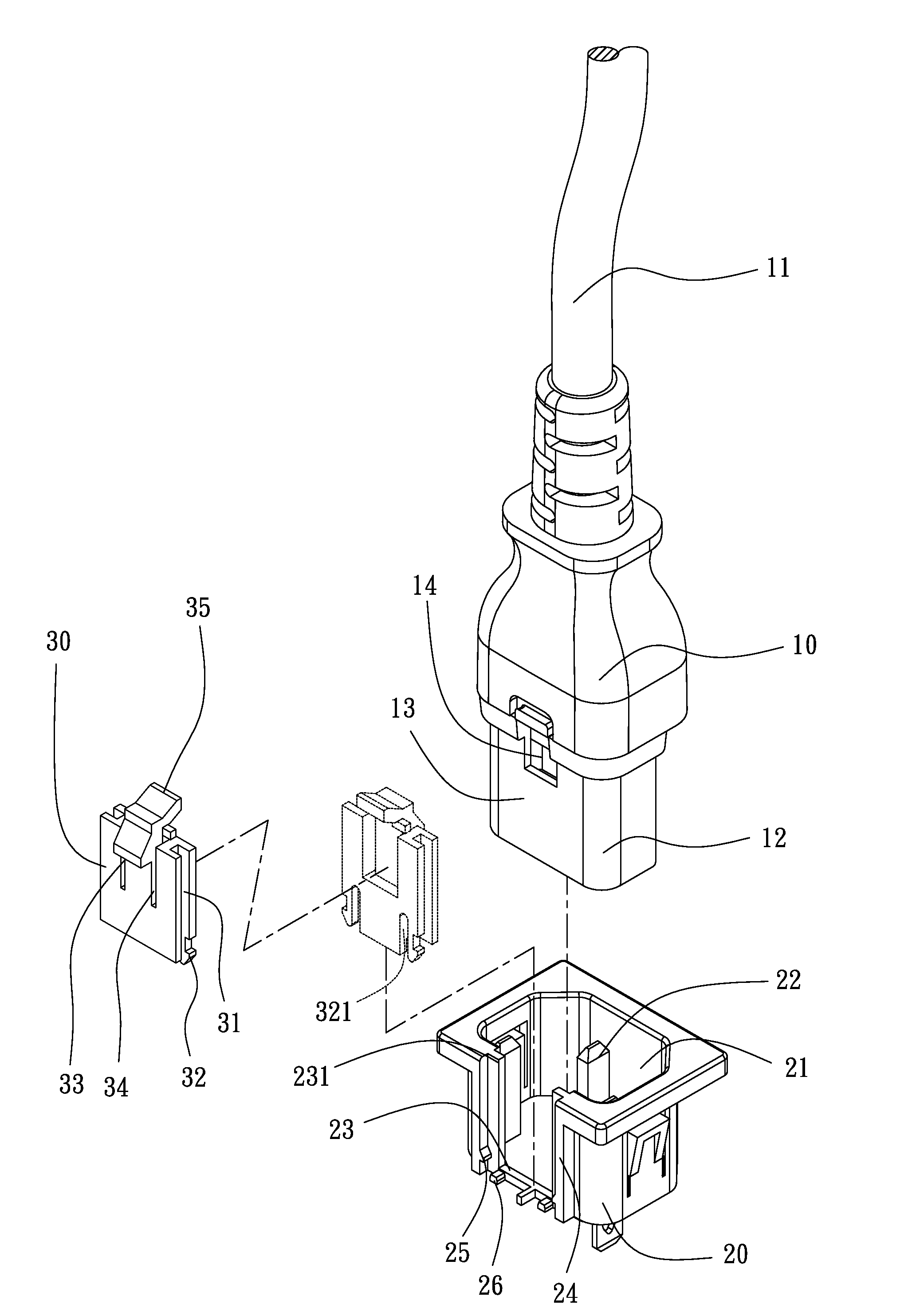
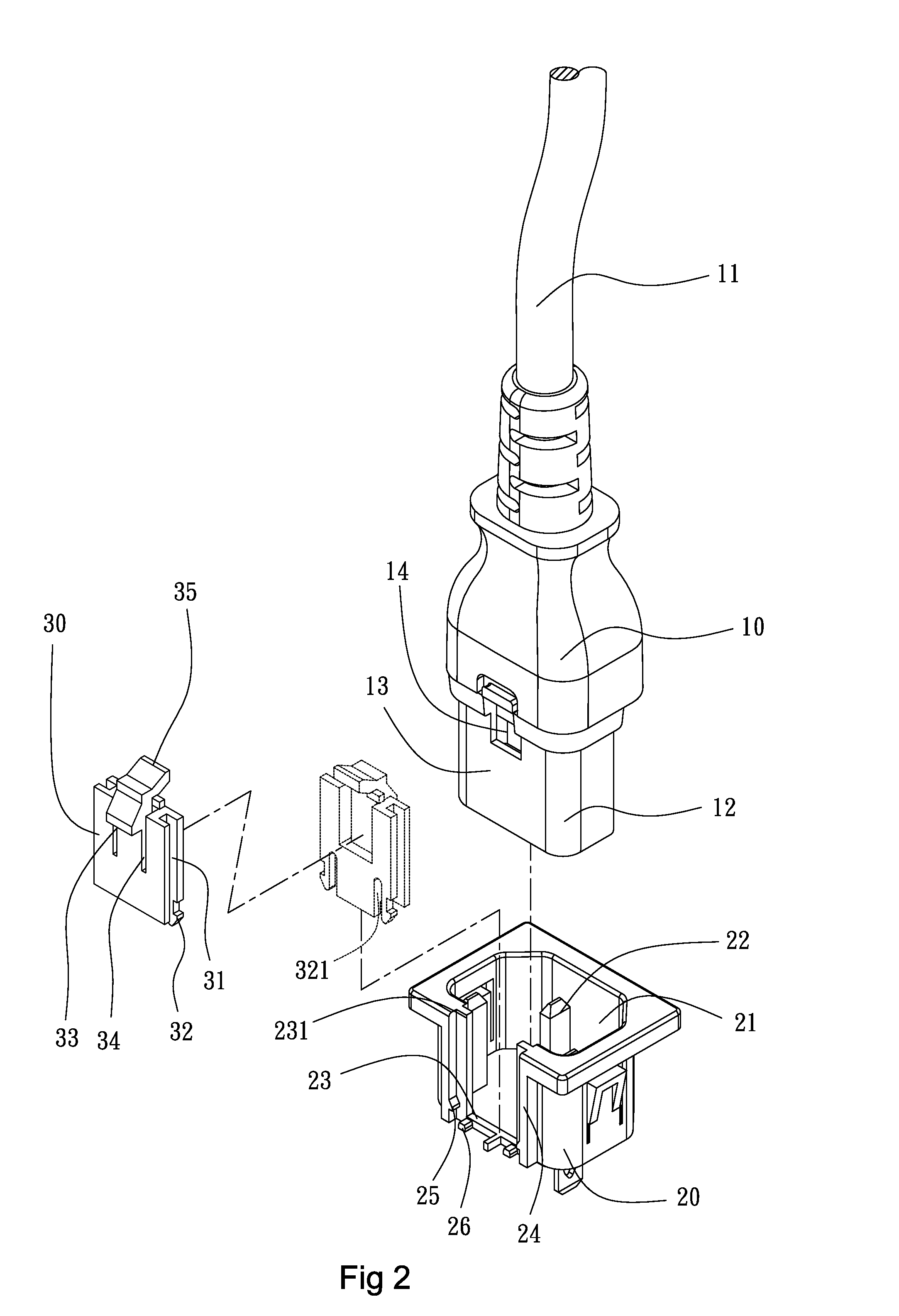
[0018]Referring to FIGS. 2-6, the present invention provides an improved fastening device of a plug-socket combination, which can be a power inlet plug-socket combination, comprises:

[0019]a plug structure 10, wherein the plug structure 10 comprises an extended connection cable 11, the plug structure 10 having a front end that forms a plug projection 12, the plug structure 10 having a side wall 13 in which a positioning cavity 14 is formed;

[0020]a socket structure 20, wherein the socket structure 20 comprises an insertion recess 21, the insertion recess 21 comprising a plurality of terminal pins 22 arranged therein in such a way that the plurality of terminal pins 22 is respectively insertable into a plurality of pin h...


PUM


Abstract

A fastening device of a plug-socket combination includes a plug structure and a socket structure. The socket structure has a side wall in which an insertion slot is formed. A plastic fastening plate includes a slit-defined barb formed on each of two sides of a lower end thereof. When the plastic fastening plate is inserted into the insertion slot, the slit-defined barbs are allowed to elastically expand to respectively engage pawls formed at a lower end of the slot. The plastic fastening plate has a free end on which a plastic pawl is formed. The plug projection of the plug structure, when jointed, through insertion, to the insertion recess of the socket structure, smoothly passes over the plastic pawl to allow the plastic pawl to spring into and thus fix the positioning cavity at the time when the positioning cavity and the plastic pawl are in alignment with each other.

Description

BACKGROUND OF THE INVENTION[0001]1. Field of the Invention[0002]The present invention relates to the field of plug and socket, and in particular to an improved fastening device of a plug-socket combination, in which a fastening plate is integrally formed with a plastic pawl through injection molding so as to provide a large engagement area, have an enhanced strength, and be not easily separated.[0003]2. The Related Arts[0004]One of the most influencing events for an industrial processing machine is unexpected interruption of power supply. The interruption of power supply may result in lowering of product yield rate and also affect the schedule of the processing operation and what is even worse is causing loss of the original processing or operation parameters. Further, power failure or interruption of power supply may lead to severe loss and damage. Conventional power plugs and sockets are often connected through plugging the blades of a plug into the slots of a socket to establish ...

Claims


Application Information

Patent Timeline
Patent Type & Authority Applications(United States)
IPC IPC(8): H01R13/627
CPCH01R13/6272H01R2103/00H01R13/6275H01R24/78
Inventor HUANG, YUNG MING
Owner RONG FENG INDAL
Learn More