Breast pump comprising heating cup

a technology of heating cup and pump, which is applied in the field of pump comprising electric heating cup, can solve the problems of irregular resistance variation, difficult detachment of pump, and occurrence of focal temperature, and achieves the effects of convenient cleaning, not easy to detach, and beautiful appearan

Inactive Publication Date: 2015-06-11
NINGBO LACTANS MEDICAL TECH
View PDF1 Cites 6 Cited by
  • Summary
  • Abstract
  • Description
  • Claims
  • Application Information

AI Technical Summary

Benefits of technology

[0018]The breast pump comprises the electric heating cup comprising the inner cover and the outer cover, and the electric heating element clamped between the inner cover and the outer cover, all of which are fabricated into an integrated structure by secondary injection molding, ultrasonic welding technology, and lathe grinding and polishing processing. The electric heating element is fixed between the inner cover and the outer cover, so it is not easy to detach, convenient for cleaning, and has impact and beautiful appearance. The conducting plates of the electric heating cup are fixed on the outer cover through secondary injection molding and are in electric connection to the contact chips at the lower front end of the host unit. Thus, the structure is simple, compact, stable and convenient for use and mass production. The resulting electric heating cup is made of opaque material, so the users cannot see the electric heating element and connection wires, providing the users with the sense of safety. Lathe grinding and polishing processing make the edge of the cup, where the inner cover and outer cover ultrasonic welded together, looks like one integrated and seamless part without any joint line visible, providing the users with the sense of hygiene.
[0019]In addition, the reinforcing ribs disposed on the inner walls of both inner cover and outer cover of the electric heating cup, ultrasonic welding protrusions, grooves, O-shaped silicone seal ring, and gaps on the cylindrical protrusion of the inner cover, on one hand, cooperate with each other to enable the inner cover and the outer cover to be connected firmly whereby forming an integrated structure, on the other hand, the resulting structure is sealed and waterproof in boiling water. In the process of boiling the electric heating cup for sterilization, air between the inner cover and the outer cover tends to inflate, thereby deforming the O-shaped silicone ring, so that the heated air breaks through the sealing of the O-shaped silicone ring and is released through the gaps. Thus, the space between the inner cover and the outer cover is approximately in the vacuum state under high temperatures, thereby preventing the electric heating cup from deforming or broken. When the heated air with high pressure releases through the gaps, air bubbles emerging in the boiling water, water is prevented to get inside of the electric heating cup. Thus, high-grade waterproof achieves, so long as the cup is taken out of the water when it is still boiling, for cooling water may be siphoned inside to the cup.
[0020]The host unit comprises a miniature diaphragm vacuum pump, a miniature magnetic valve, and an air loop comprising an air inlet and an air outlet. The suction pipe of the host unit mentioned above also acts as the air inlet of the air loop. An air inlet of the miniature diaphragm vacuum pump and an air outlet of the miniature magnetic valve communicate with each other and both are connected to the air inlet of the air loop; an air inlet of the magnetic valve and an air outlet of the miniature diaphragm vacuum pump are both connected to the air outlet of the air loop. To clean the breast pump, the air inlet of the air loop and the air outlet of the air loop each are connected to straws. The straw of the air inlet is inserted into a container containing medical alcohol, and the straw of the air outlet is inserted into a hollow container. Start the breast pump in the cleaning mode, the medical alcohol fluid is siphoned to every space of the air loop under the drive of the vacuum pump, whereby completely disinfecting the breast pump, each cleaning lasts for only about 10 seconds, and finally the effluent is collected by the hollow container. On this occasion, the vacuum pump acts as a water pump temporarily. After that, move the air inlet away from the medical alcohol and remain the breast pump working for a while, the alcohol residue evaporates quickly and the air loop and the diaphragm vacuum pump remain dry to protect the mechanical properties of the diaphragm vacuum pump and insure the service life of the breast pump.

Problems solved by technology

Thus, the breast pump has a complex structure and manufacturing process.
In addition, the heating element is subject to the natural properties of the carbon fiber, which often has disadvantages such as nonuniform hot spots, irregular resistance variation, and the occurrence of focal temperature.
Furthermore, conventional breast pumps are difficult to clean and sterilize thoroughly, as the abundant particles of fat and protein of the aerosolized milk tends to precipitate and accumulate in the inner walls of air path including pipes and diaphragms and gas drums of the pumps, which go bad in hours and bacteria thrives to be a source of pollution to the fresh milk in the container and a health risk to the mother's breasts.

Method used


Image

  • Breast pump comprising heating cup
  • Breast pump comprising heating cup
  • Breast pump comprising heating cup

Examples


Embodiment Construction

[0029]For further illustrating the invention, experiments detailing of a breast pump are described below. It should be noted that the following examples are intended to describe and not to limit the invention.

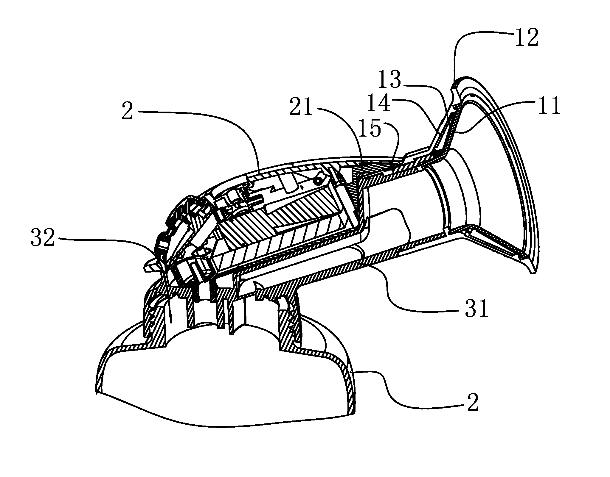
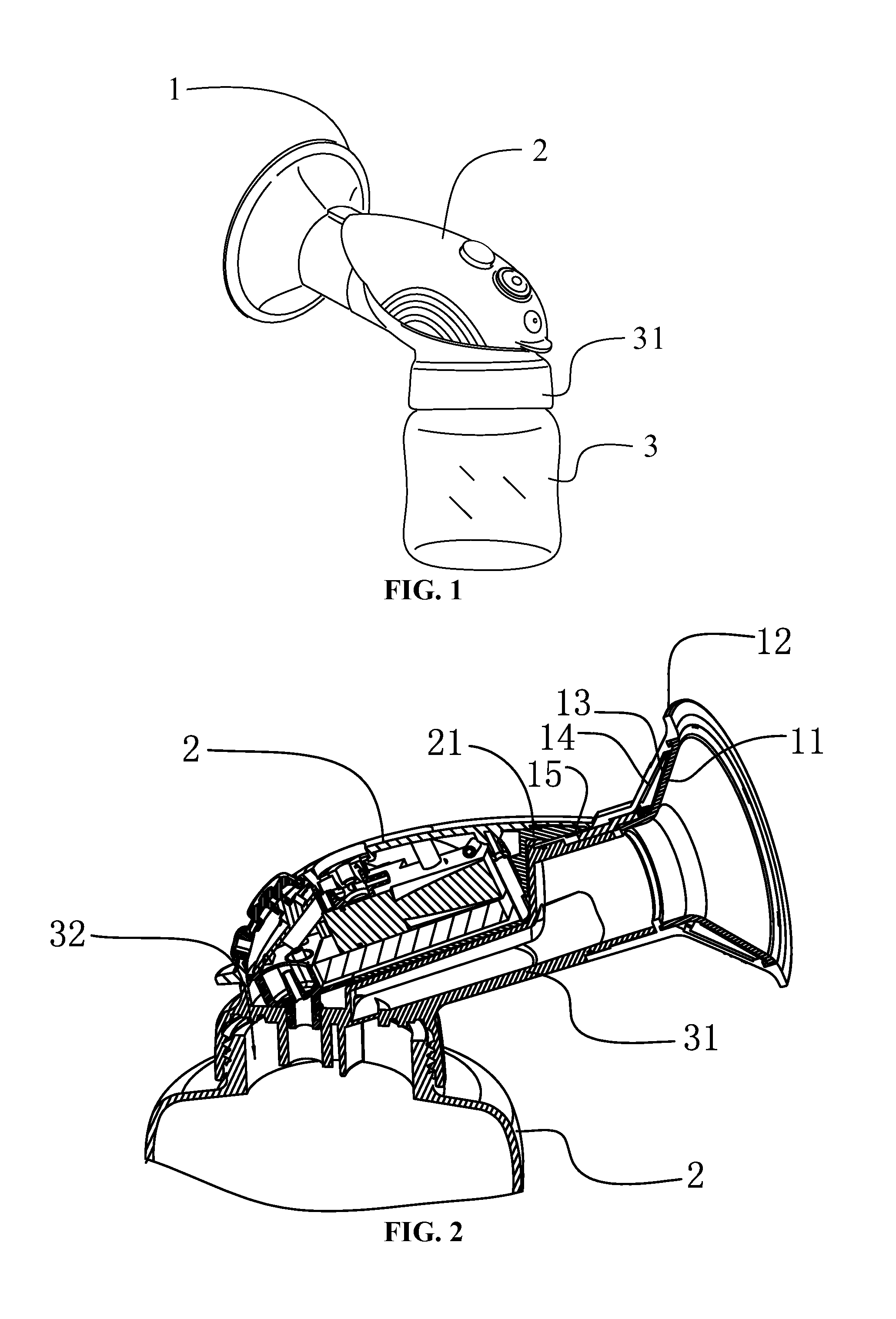
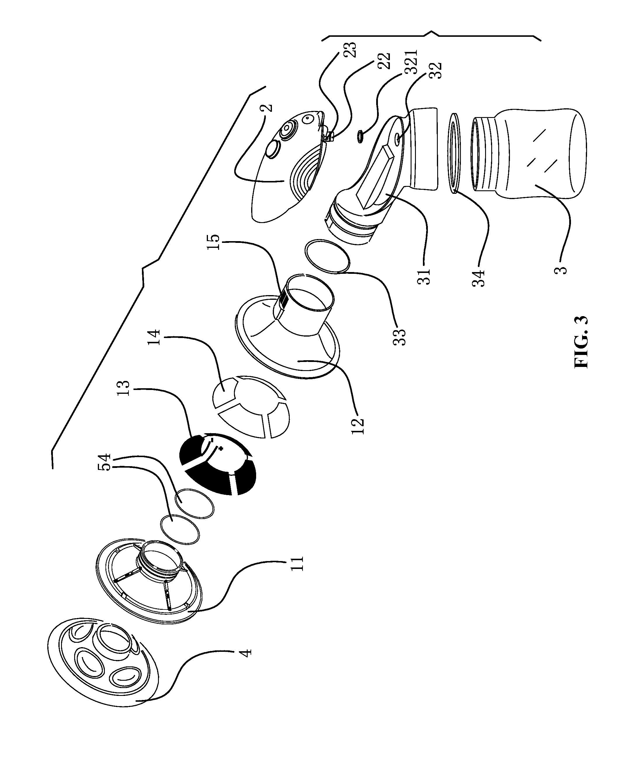
[0030]As shown in FIGS. 1-6, a breast pump of the invention comprises a container 3, a host unit 2 disposed above and communicating with the container, an electric heating cup 1 disposed at the front end of the host unit 2 and communicating with the container 3. The host unit 2 comprises a miniature diaphragm vacuum pump, a miniature magnetic valve configured to generate vacuum negative pressure, an air loop comprising an air inlet and an air outlet, an integrated circuit board, and a rechargeable lithium polymer battery for supply power for the breast pump. The front end of the electric heating cup 1 is in the shape of a horn, and its diameter is slightly larger than that of a mother's areola, so that the electric heating cup 1 better contacts the areola. The rear end of the e...


PUM


Abstract

A breast pump including a container, a host unit disposed above and communicating with the container, an electric heating cup disposed at the front end of the host unit and communicating with the container, an electric heating element, and heat insulation. The electric heating cup includes an inner cover and an outer cover which are integrated. The electric heating element and the heat insulation are disposed between the inner cover and the outer cover. The heat insulation is disposed between the electric heating element and the outer cover. Positive and negative electrodes of the electric heating element are connected to conducting plates disposed in the inner side of the outer cover via connection wires. The conducting plates extend to the outer side of the outer cover and are in electric connection to contact chips disposed at the lower front end of the host unit.

Description

CROSS-REFERENCE TO RELATED APPLICATIONS[0001]This application is a continuation-in-part of International Patent Application No. PCT / CN2013 / 000947 with an international filing date of Aug. 12, 2013, designating the United States, now pending, and further claims priority benefits to Chinese Patent Application No. 201210290386.5 filed Aug. 15, 2012. The contents of all of the aforementioned applications, including any intervening amendments thereto, are incorporated herein by reference. Inquiries from the public to applicants or assignees concerning this document or the related applications should be directed to: Matthias Scholl P.C., Attn.: Dr. Matthias Scholl Esq., 245 First Street, 18th Floor, Cambridge, Mass. 02142.BACKGROUND OF THE INVENTION[0002]1. Field of the Invention[0003]The invention relates to a breast pump comprising an electric heating cup.[0004]2. Description of the Related Art[0005]A typical breast pump employs carbon fiber, which is disposed outside the bell mouth the...

Claims


Application Information

Patent Timeline
Patent Type & Authority Applications(United States)
IPC IPC(8): A61M1/06A61F7/00
CPCA61M1/062A61F2007/0021A61M2205/3633A61F7/007A61M2205/3653A61M2205/8206A61M1/064A61F2007/0088
Inventor HU, MIN
Owner NINGBO LACTANS MEDICAL TECH
Why Eureka
Try Eureka