Sheet manufacturing apparatus, sheet manufacturing method, sheet manufactured using sheet manufacturing apparatus and sheet manufacturing method, and composite and container used in sheet manufacturing apparatus and sheet manufacturing method

a technology of sheet manufacturing and manufacturing method, which is applied in the field of sheet, can solve the problems of difficult scaling down the size of the apparatus, difficult to respond to recent demands for energy saving, and large amount of energy and time used for this, and achieve excellent uniformity, excellent dispersion of resin, and high amount of charge in the particles as a resul

Active Publication Date: 2018-01-16
SEIKO EPSON CORP
View PDF29 Cites 6 Cited by
  • Summary
  • Abstract
  • Description
  • Claims
  • Application Information

AI Technical Summary

Benefits of technology

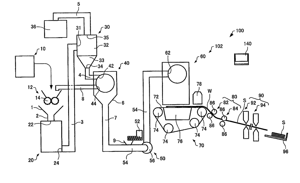
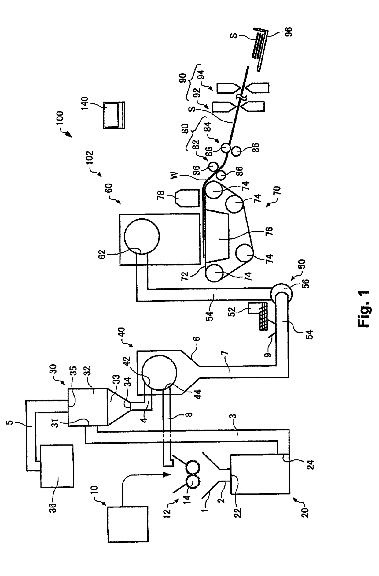
[0014]According to this sheet manufacturing apparatus, it is easy for the composite to become attached to the fibers due to the composite becoming charged when mixing and it is difficult for the composite to become detached from the fibers when the web is formed since the composite where the wax and the resin are integrally combined is mixed with the fibers in air. Then, it is possible to manufacture an appropriately strong sheet since the composite and the fibers are bonded.
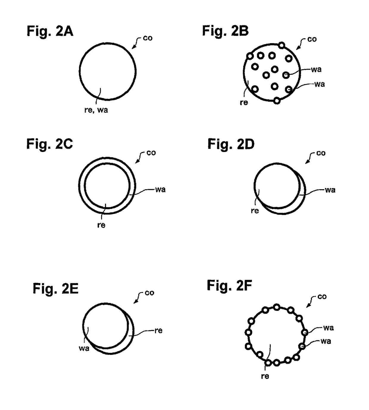
[0036]With this composite, detaching of the resin is suppressed when a web is formed by the composite being mixed with fibers.

Problems solved by technology

However, it is necessary to use a large amount of water since the paper forming method is a wet type of method, and there is a necessity for water to be discharged, drying to be carried out, and the like after the paper is formed and the amount of energy and time which is used for this is extremely large.
Accordingly, it is becoming difficult to respond to recent demands for energy savings, protection of the environment, and the like.
In addition, it is often the case that large-scale utilities and infrastructure such as water, power, and water discharge facilities are necessities for the apparatus which is used in the sheet forming method and scaling down the size of the apparatus is difficult.
However, the thermal bonding resin in the technique described in Japanese Unexamined Patent Application Publication No. 2011-099172 has the properties of a powder and there is a concern about the resin detaching from between the fibers during an air laid process.
It is described in paragraph of Japanese Unexamined Patent Application Publication No. 2011-099172 that the thermal bonding powder passes through the gaps in the mesh conveyor (mesh belt) when the thermal bonding powder is small and it is difficult for the thermal bonding powder to be fixed between the fibers.
However, when the particle diameter of the resin is large, the uniformity of dispersion of the resin over the manufactured sheet deteriorates.
For this reason, a design is necessary such that it is difficult for resin to become detached from between the fibers even when the particle diameter of the resin is small.
According to this sheet manufacturing apparatus, it is easy for the composite to become attached to the fibers due to the composite becoming charged when mixing and it is difficult for the composite to become detached from the fibers when the web is formed since the composite where the wax and the resin are integrally combined is mixed with the fibers in air.
In addition, it is difficult for there to be any effects from gravity and detaching is also difficult since the composite is small.
According to this aspect of the sheet manufacturing apparatus, it is easy for the composite to become charged and it is difficult for the composite to become detached from the fibers due to the fibers and the composite being passed through the rotating units which have blades which rotate.
With this container, it is possible to easily transport and store the composite where the resin and the wax are integrally combined and which has an effect in that it is difficult for the composite to become detached when being used by being mixed with fibers.

Method used


Image

  • Sheet manufacturing apparatus, sheet manufacturing method, sheet manufactured using sheet manufacturing apparatus and sheet manufacturing method, and composite and container used in sheet manufacturing apparatus and sheet manufacturing method
  • Sheet manufacturing apparatus, sheet manufacturing method, sheet manufactured using sheet manufacturing apparatus and sheet manufacturing method, and composite and container used in sheet manufacturing apparatus and sheet manufacturing method
  • Sheet manufacturing apparatus, sheet manufacturing method, sheet manufactured using sheet manufacturing apparatus and sheet manufacturing method, and composite and container used in sheet manufacturing apparatus and sheet manufacturing method

Examples


experiment examples

6. Experiment Examples

[0144]Experiment examples are shown below and the present invention will be further described, but the present invention is not limited in any way by the examples below.

6.1. Composite Manufacturing Method

[0145]Coarsely pulverized material A which are carnauba wax are obtained by repeating an operation of carnauba wax (melting point of 86° C.) being processed for 45 seconds and rested for 120 seconds four times or more in a high speed mill (HS-20 manufactured by Scenion Inc.).

[0146](1) 9.7 kg of polyester resin (glass transition point of 54° C. and softening temperature of 96° C.)

[0147](2) 0.3 kg of coarsely pulverized material A of carnauba wax

[0148]After the materials described above are mixed, a pellet is obtained by cutting a strand, which is output by introducing the materials described above into a twin screw kneading extruder and melting and kneading the materials described above at 80° C. to 120° C., into lengths of 5 mm. The pellet is introduced again i...


PUM

PropertyMeasurementUnit
sizeaaaaaaaaaa
lengthsaaaaaaaaaa
lengthsaaaaaaaaaa

Abstract

A sheet manufacturing apparatus includes a mixing unit and a forming unit. The mixing unit is configured to mix fibers and a composite, where a resin and a wax are integrally combined, in air. The forming unit is configured to form a sheet by depositing and heating a mixed material where the fibers and the composite are mixed.

Description

CROSS-REFERENCE TO RELATED APPLICATIONS[0001]This application claims priority to Japanese Patent Application No. 2014-182998 filed on Sep. 9, 2014. The entire disclosure of Japanese Patent Application No. 2014-182998 is hereby incorporated herein by reference.BACKGROUND[0002]Technical Field[0003]The present invention relates to a sheet manufacturing apparatus, a sheet manufacturing method, a sheet which is manufactured using the sheet manufacturing apparatus and the sheet manufacturing method, and a composite and a container which are used in the sheet manufacturing apparatus and the sheet manufacturing method.[0004]Related Art[0005]Obtaining a formed body with a sheet shape or a film shape is performed in the past by accumulating a substance with a fibrous form and utilizing the mutual bonding force between fibers which are accumulated. As a representative example, there is the example of manufacturing paper by forming sheets using water. Sheet forming methods are currently widely ...

Claims


Application Information

Patent Timeline
Patent Type & Authority Patents(United States)
IPC IPC(8): C08L91/06D04H1/587B05D3/00D04H1/60D04H1/732C08L67/00
CPCC08L91/06B05D3/007D04H1/732D04H1/587D04H1/60C08L67/00
Inventor UENO, YOSHIHIRO
Owner SEIKO EPSON CORP
Why Eureka
Try Eureka