Method and apparatus for feeding electric energy into an electric supply grid

a technology of electric energy supply and electric supply grid, which is applied in the direction of electric generator control, dynamo-electric converter control, machines/engines, etc., can solve the problems that the current problem in the supply grid might not be completely resolved, and achieve the effect of stable operating point, more stable and less affecting the voltage at the grid connection poin

Active Publication Date: 2015-10-01
WOBBEN PROPERTIES GMBH
View PDF7 Cites 30 Cited by
  • Summary
  • Abstract
  • Description
  • Claims
  • Application Information

AI Technical Summary

Benefits of technology

[0035]According to one embodiment, it is proposed that, when incorporating the at least one grid characteristic, characteristics, or at least one characteristic, of the generator are (or is) to be considered as well, and that a short circuit current ratio is to be incorporated. The grid characteristics of the connection node are also incorporated on this power supply in consideration of the characteristics of the generator. Preferably, it is proposed that the generator be controlled with a short circuit current ratio of <6. Preferably, the short circuit current ratio is hereby <4, and in particular <2. Thus, a control method is suggested for a short circuit current ratio that is smaller than usual. This often requires that this specific design be implemented or at least accepted. It is deliberately proposed to feed into a weak grid, namely in particular with a generator, the connected load of which is large compared to the short circuit power of the grid with regard to the connection point, namely larger than one sixth, larger than a quarter or even larger than half the short circuit power of the grid for this connection point. It has thereby been recognized that using a wind power installation with a voltage source converter can simply be referred to as a voltage converter, in particular with a full converter structure, the operation of which is facilitated in a weak grid. It is deliberately accepted that by choosing or accepting a low short circuit current ratio, operation will occur near a stability boundary. It has been recognized that a control with a voltage converter can secure a respective control, in particular a respective fast and accordingly precise control of the feed-in. As a result, the grid connection points that have so far been regarded as unsuitable can now be used to connect a generator.
[0041]Preferably, during operation, the stability reserve of the actual operating point is constantly observed and, in particular, the operating point is changed if the distance to the stability reserve is reduced, especially if it falls below the value of the respective stability reserve. This observation can be made online or quasi-online, i.e., with small time differences between the observation times and / or through a dynamic observer with a slight time delay. This can be used to respond quickly and at very short notice to changes which are relevant to stability, and thus to secure a stable operation even near the stability boundary.
[0044]Preferably, a threatening loss of stability on the grid connection point is detected and / or shown. This is to avoid an interruption of the feed-in, or to prepare the generator for a quick return feeding in case of a loss of stability.
[0052]Further, the current grid condition can have an impact on the sensitivity of the voltage at the grid connection point. For example, if the grid is less sensitive to external factors, the voltage at the grid connection point is more stable if the grid, in particular with regard to the grid connection point, functions in a stable operating point. Conversely, the voltage on the grid connection point can be more easily influenced if the grid functions in a less stable operating point, such as an operating point at which, in the case of a wind power installation, the plant is already supporting the grid.
[0053]For example, a wind power installation can support the grid by feeding in reactive power. Preferably, it is therefore proposed that the grid sensitivity be determined in accordance with the partial discharge of the voltage at the grid connection point according to the fed-in reactive power. If there is a strong voltage change at the grid connection point with a change in the fed-in reactive power, the result is a high grid sensitivity, i.e., the voltage can be more easily influenced.

Problems solved by technology

However, an adaption to new situations, i.e., to changed conditions in the supply grid, carries the risk that any current problems in the supply grid might not be completely resolved.

Method used


Image

  • Method and apparatus for feeding electric energy into an electric supply grid
  • Method and apparatus for feeding electric energy into an electric supply grid
  • Method and apparatus for feeding electric energy into an electric supply grid

Examples


Embodiment Construction

[0072]Below, identical reference signs for similar, but non-identical elements may be provided, or they can also be provided for elements that are only illustrated schematically or symbolically, and that may have different details, but which are not relevant for the respective explanation.

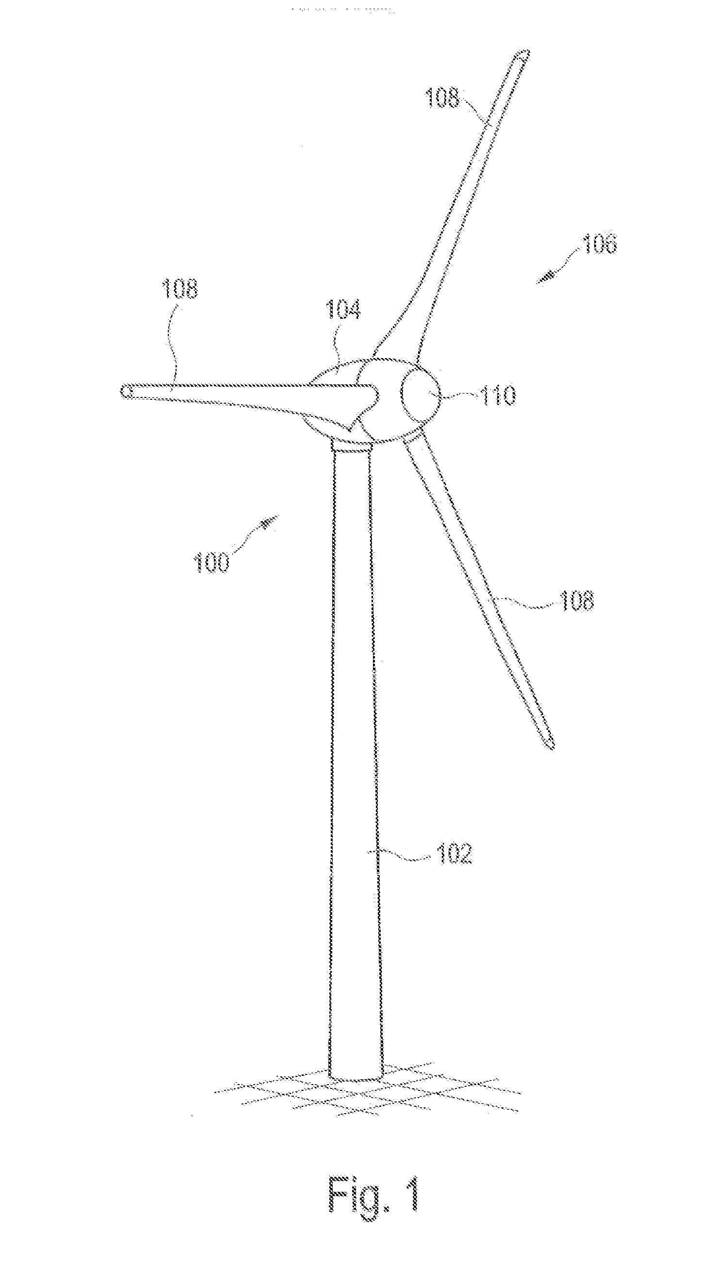
[0073]FIG. 1 Shows wind power installation 100 with tower 102 and nacelle 104. Rotor 106 with three rotor blades 108 and spinner 110 is located on nacelle 104. Rotor 106 is set in operation by the wind in a rotating movement, thereby driving a generator in nacelle 104.

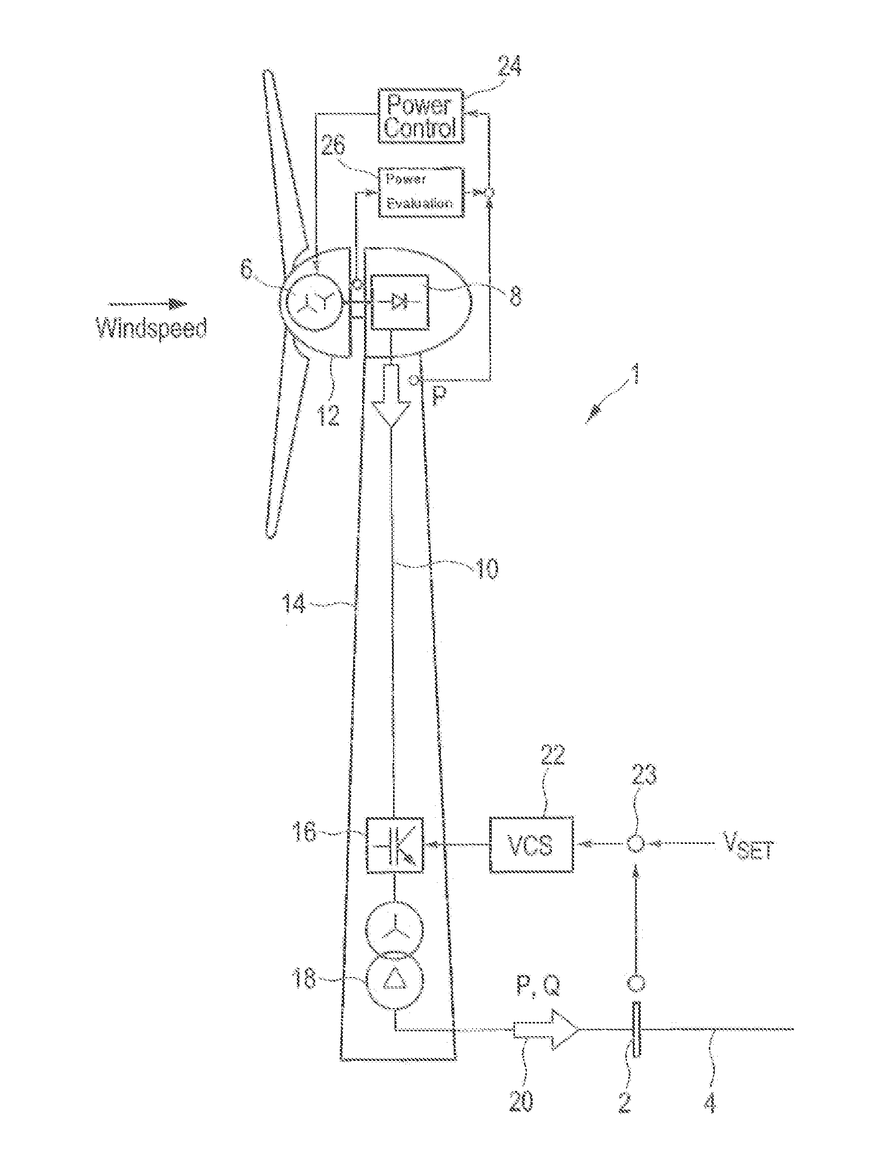
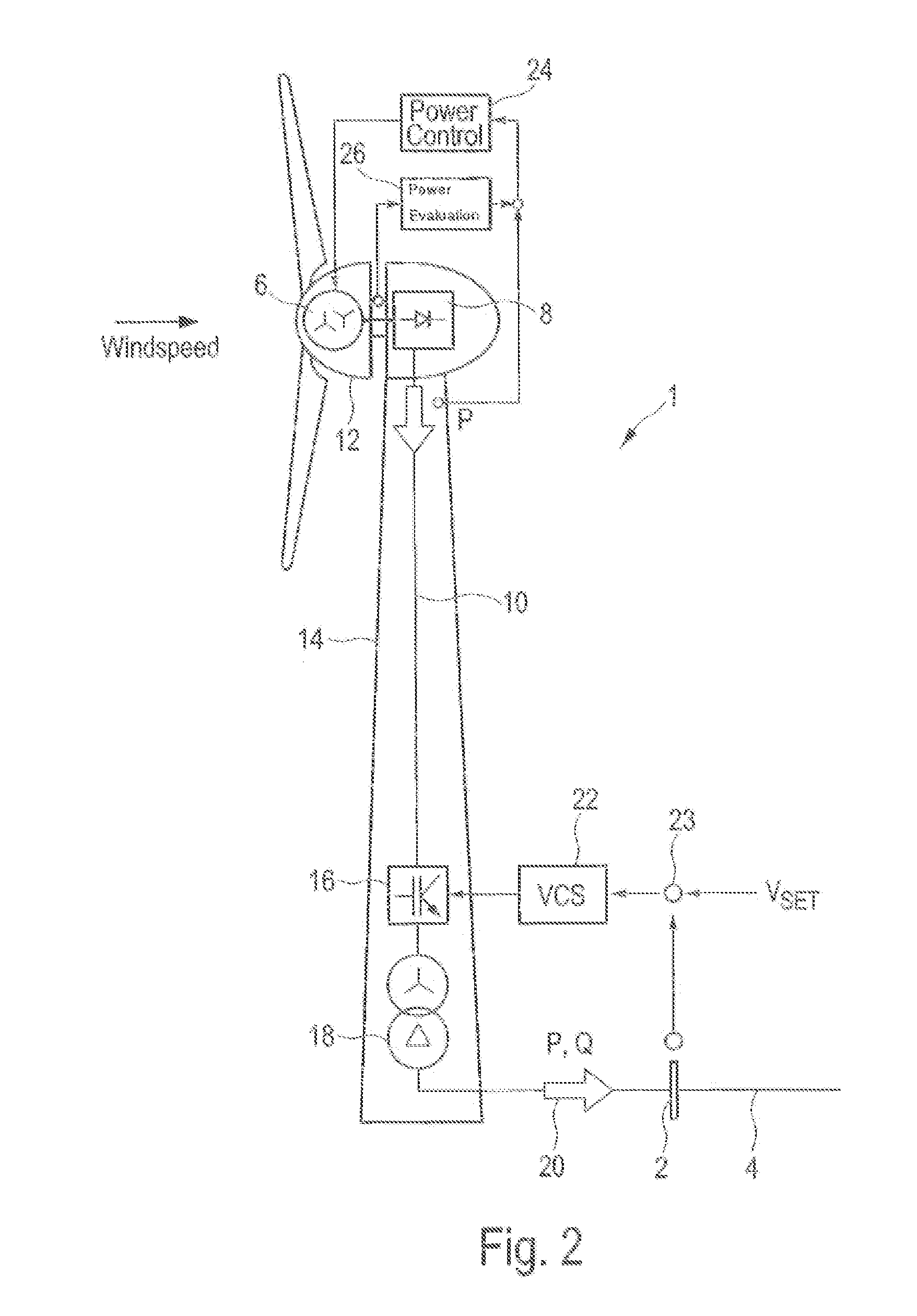
[0074]FIG. 2 shows a schematic view of a wind power installation 1 connected to electric supply grid 4 over grid connection point 2. Electric supply grid 4 is simply referred to as grid 4 or grid 4, whereby these terms are used synonymously.

[0075]Wind power installation 1 comprises generator 6, which is driven by the wind, thereby generating electric energy. In one of the embodiments, generator 6 is an electrically excited multiphase ...


PUM


Abstract

The invention relates to a method for controlling a generator of electric energy that is connected to an electric supply grid on a grid connection point, comprising the following steps: incorporating at least one grid characteristic of the electric supply grid related to the grid connection point, and controlling the generator in such way that it feeds power into the electric supply grid depending on the incorporated grid characteristic.

Description

BACKGROUND[0001]1. Technical Field[0002]The present invention relates to a method for controlling a generator of electric energy which is connected to an electric supply grid in a grid connection point. In addition, the present invention relates to such a generator of electric energy.[0003]2. Description of the Related Art[0004]Feeding electric energy into an electric supply grid, such as the European grid or the US power grid, is generally known. The electric supply grid as described below refers to the widely accepted AC voltage grid. This does not exclude the presence of DC voltage sections in the grid. Likewise, frequency-independent aspects may generally also refer to a DC voltage grid. Historically, energy is fed into an electric supply grid with a large power station that drives a synchronous generator using primary energy, such as coal, nuclear energy or gas. Depending on the number of pole pairs and the speed of the synchronous generator, this generator feeds into the suppl...

Claims


Application Information

Patent Timeline
Patent Type & Authority Applications(United States)
IPC IPC(8): H02P9/10F03D9/00H02P9/02
CPCH02P9/105F03D9/005H02P9/02H02J3/386H02J3/241F03D7/0284F05B2270/337F03D9/255F03D9/257Y02E10/72
Inventor DIEDRICHS, VOLKERBUSKER, KAIBEEKMANN, ALFRED
Owner WOBBEN PROPERTIES GMBH
Why Eureka
Try Eureka