Control apparatus, image input apparatus, and control methods thereof

a control apparatus and image technology, applied in the field of control apparatus, image input apparatus, and control methods thereof, can solve the problem of increasing the load placed on the user, and achieve the effect of performing easily and accurately

Active Publication Date: 2015-10-01
CANON KK
View PDF3 Cites 11 Cited by
  • Summary
  • Abstract
  • Description
  • Claims
  • Application Information

AI Technical Summary

Benefits of technology

[0010]The present invention provides a technique with which interlock control of a plurality of apparatuses can be performed easily and accurately.
[0027]According to the present invention, interlock control of a plurality of apparatuses can be performed easily and accurately.

Problems solved by technology

However, a plurality of cameras may be connected to a monitor, and not all of the plurality of cameras are necessarily targets of interlock control.
As a result, a load placed on the user increases, and a camera may be selected erroneously.

Method used


Image

  • Control apparatus, image input apparatus, and control methods thereof
  • Control apparatus, image input apparatus, and control methods thereof
  • Control apparatus, image input apparatus, and control methods thereof

Examples


first embodiment

[0048]A system according to a first embodiment of the present invention will now be described with reference to the drawings.

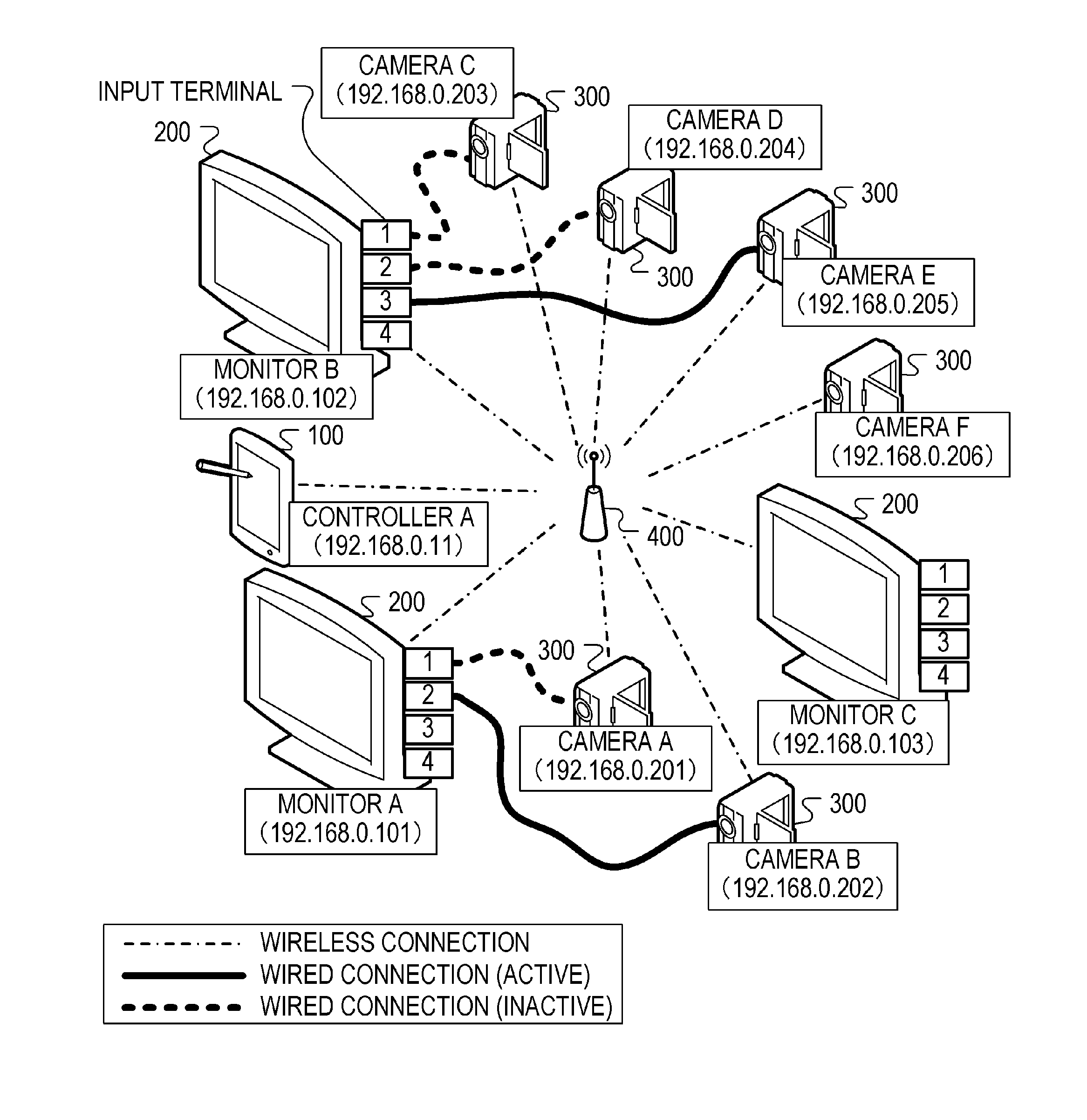
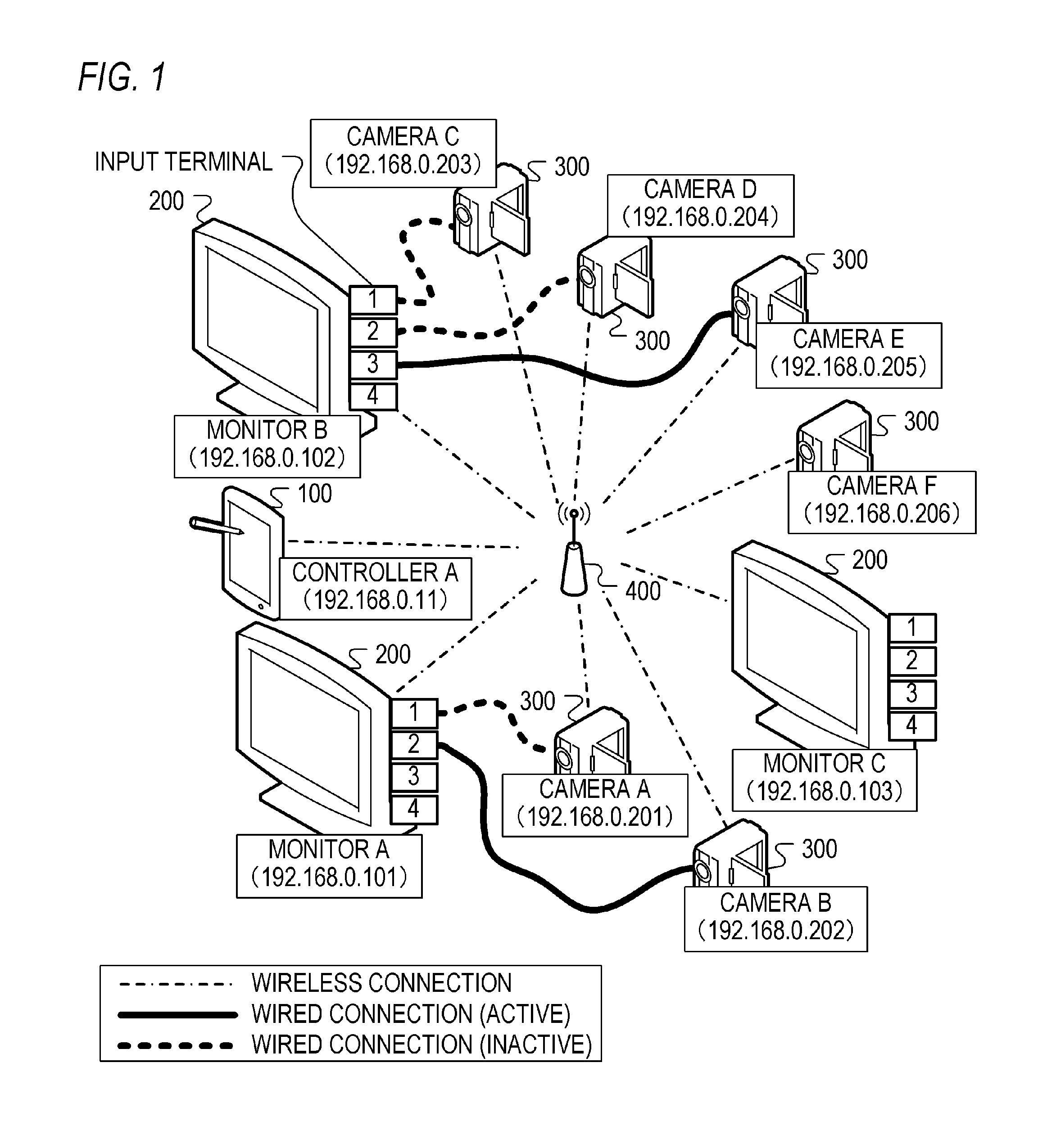
[0049]FIG. 1 is a view showing an example of a connection configuration of the system according to this embodiment. As shown in FIG. 1, the system according to this embodiment includes a controller 100, a monitor 200, a camera 300, and an access point 400. The controller 100, the monitor 200, the camera 300, and the access point 400 together constitute a wireless LAN (Local Area Network). The controller 100, the monitor 200, and the camera 300 are connected to each other communicably. More specifically, the controller 100, the monitor 200, and the camera 300 are connected wirelessly to the access point 400. Communication between the controller 100, the monitor 200, and the camera 300 is performed by the access point 400.

[0050]Note that the monitor 200 and the camera 300 may be connected to the controller 100 without passing through the access point 400. In thi...

second embodiment

[0179]A system according to a second embodiment of the present invention will now be described with reference to the drawings.

[0180]In this embodiment, a case in which operating modes suitable for inputting and outputting RAW data (image data in a RAW format) are set when interlock control of the camera and the monitor is performed will be described.

[0181]The system according to this embodiment is configured largely identically to that of FIG. 1 illustrating the first embodiment.

[0182]In FIG. 1, the output mode for outputting image data in the color gamut prescribed by ITU-R Rec. BT. 709 is set in the camera B. Further, the input mode that is suitable for inputting image data in the color gamut prescribed by ITU-R Rec. BT. 709 is set in the monitor A.

[0183]In FIG. 1, when the output mode of the camera B is switched to an output mode for outputting RAW data, RAW data are output from the camera B. In other words, the camera B can output image data without a reduction in the dynamic ra...

third embodiment

[0211]A system according to a third embodiment of the present invention will now be described with reference to the drawings.

[0212]In this embodiment, an example of a case in which a plurality of cameras have active connections to a monitor, such as a case in which multi-screen display is performed on the monitor, will be described.

[0213]FIG. 15 is a view showing an example of a connection configuration of the system according to this embodiment.

[0214]In FIG. 1 illustrating the first embodiment, the input terminal 2 is the only active input terminal of the monitor A, but in FIG. 15, both the input terminal 1 and the input terminal 2 of the monitor A are active. FIG. 15 is otherwise identical to FIG. 1.

[0215]In FIG. 15, the camera A is connected to the input terminal 1 of the monitor A and the camera B is connected to the input terminal 2 of the monitor A. The monitor A displays the image data output from the camera A and the image data output from the camera B on two screens. Furthe...


PUM


Abstract

A control apparatus capable of controlling a plurality of apparatuses including at least one image output apparatus that outputs image data and at least one image input apparatus into which image data are input, includes: a first obtaining unit configured to obtain, from one of a first apparatus that serves as the image input apparatus among the plurality of apparatuses and a second apparatus that serves as the image output apparatus among the plurality of apparatuses and outputs image data input into the first apparatus, pair information identifying the first apparatus and the second apparatus; and a control unit configured to perform interlock control of the first apparatus and the second apparatus on the basis of the pair information.

Description

BACKGROUND OF THE INVENTION[0001]1. Field of the Invention[0002]The present invention relates to a control apparatus, an image input apparatus, and control methods thereof.[0003]2. Description of the Related Art[0004]Recently, images are produced by photographing image data in various formats. For example, image data having a wide dynamic range (HDR (High Dynamic Range) image data) may be photographed. Accordingly, apparatuses that are suitable for inputting and outputting image data in various formats are used as a photographic apparatus (a camera) and an image display apparatus (a monitor) during image production. The format of the input and output image data is typically switched in response to a user operation (a user operation to set operating modes of the apparatuses, for example). To display image data output from the camera accurately on the monitor, an operating mode that is suitable for inputting the image data output from the camera must be set as the operating mode of th...

Claims


Application Information

Patent Timeline
Patent Type & Authority Applications(United States)
IPC IPC(8): H04N5/232H04N1/00H04N1/327H04N5/247H04N7/18
CPCH04N5/23206H04N5/247H04N5/23229H04N7/181H04N2201/0039H04N1/00251H04N1/00344H04N2201/3205H04N2201/0015H04N1/32767H04N23/661H04N23/90
Inventor MITO, KOJI
Owner CANON KK
Why Eureka
Try Eureka