Microwave oven

a technology of micro-wave ovens and user interfaces, which is applied in microwave heating, electrical/magnetic/electromagnetic heating, electrical apparatus, etc., can solve the problems of difficult use or confusion of user interfaces of many microwave ovens, and the difficulty of locating the platters on the roller mechanism

Active Publication Date: 2015-10-01
BREVILLE HLDG PTY LTD
View PDF6 Cites 12 Cited by
  • Summary
  • Abstract
  • Description
  • Claims
  • Application Information

AI Technical Summary

Benefits of technology

[0046]Preferably, the damping element operates to dampe

Problems solved by technology

The user interfaces of many microwave ovens are difficult to use or confusi

Method used


Image

  • Microwave oven
  • Microwave oven
  • Microwave oven

Examples


Embodiment Construction

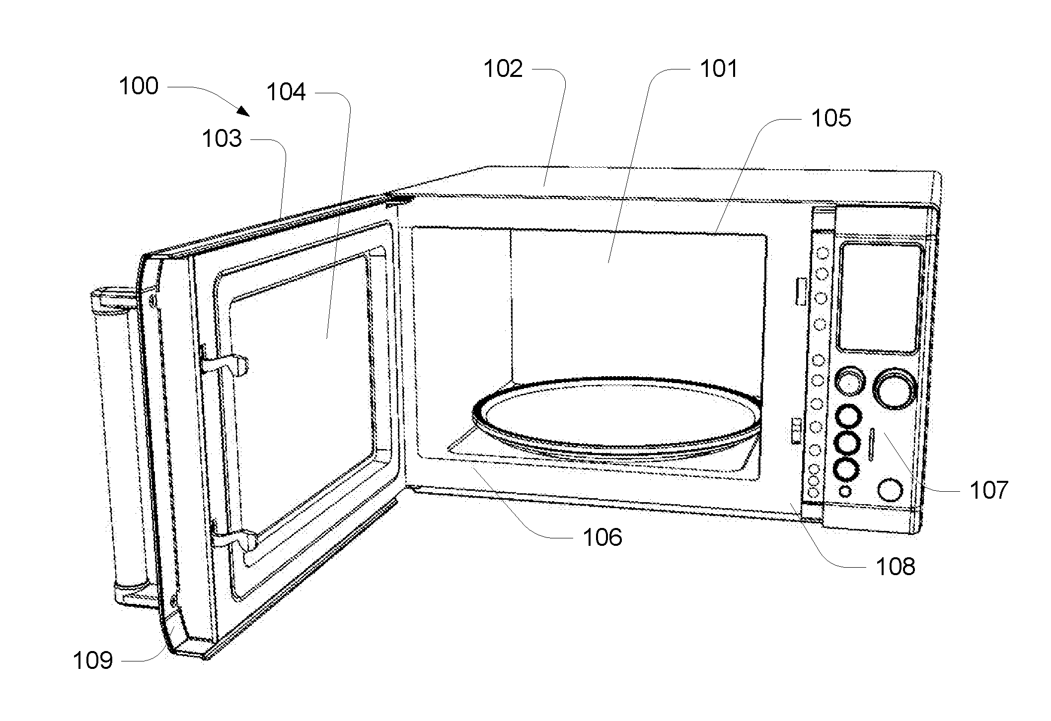
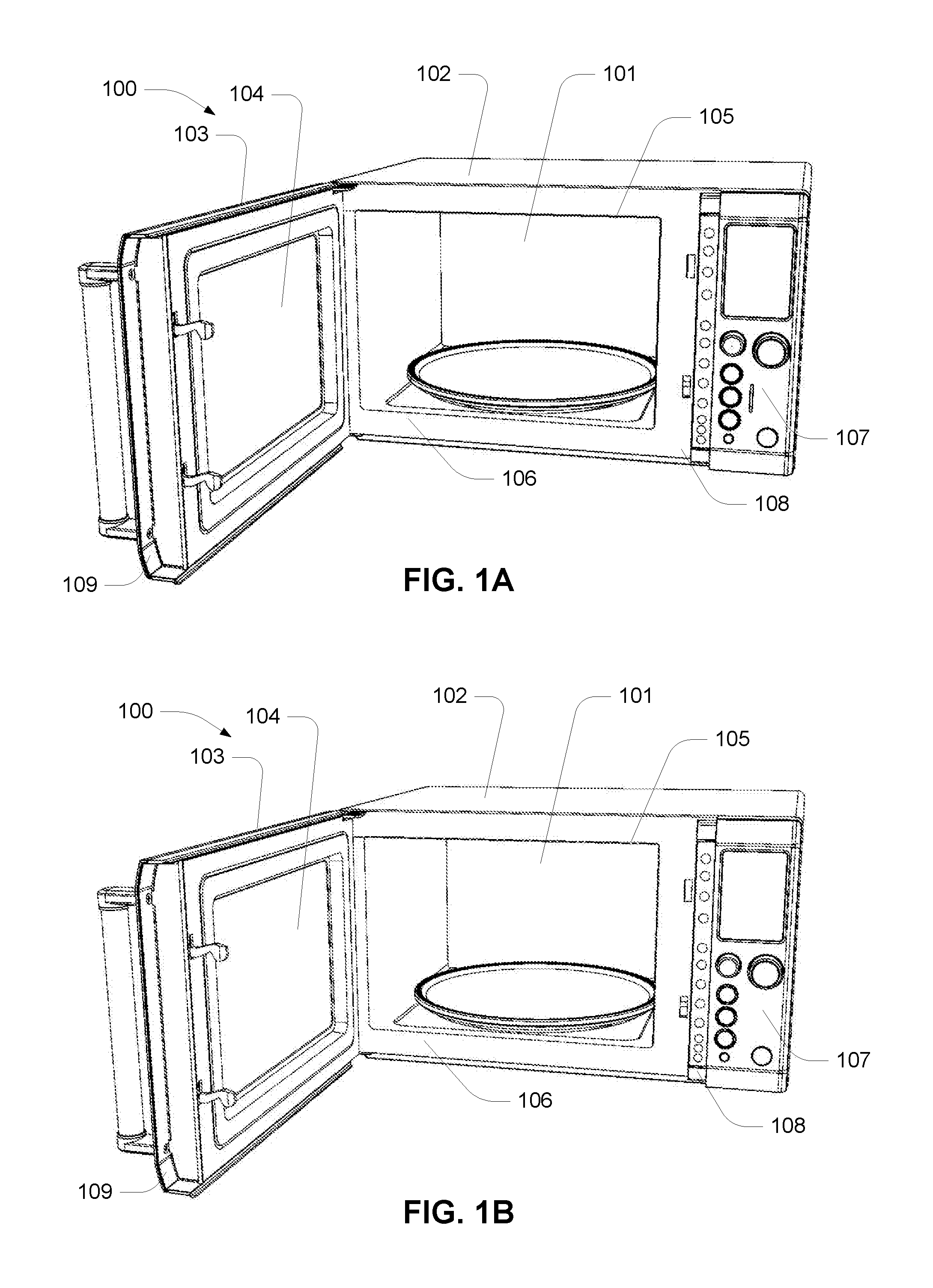
[0101]As shown in FIG. 1, a microwave oven 100 comprises a cooking chamber or cavity 101 that is contained within an enclosure or housing 102. The cavity 101 has a hinged door 103 with a central view window 104. The mouth opening 105 of the cavity 101 is surrounded by a flat landing 106 against which the door 103 closes and seals. The landing 106 is recessed with respect to the oven's user interface 107. When the oven door 103 is closed, the front surfaces of the door 103 and the interface 107 are generally flush. The oven 100 also provides an auxiliary controls 108 that are adjacent to the opening 105 and recessed with respect to the front surface of the user interface 107. The controls 108 are covered by a rim 109 of the free edge of the door 103, when the door is closed. As will be explained, the auxiliary control panel 108 comprises flush switches that provide enhanced control over the oven. In preferred embodiments, membrane type switches are used on the auxiliary panel 108.

[01...


PUM


Abstract

A user interface for a microwave oven. The user interface including: a power input element for receiving user input to adjust a cooking power setting; a time input element for receiving user input to adjust a cooking time setting; a display element for displaying the cooking power setting and the cooking time setting; and a processor module that receives a first signal from the power input element that is indicative of an adjustment to a cooking power setting and a second signal from the time input element that is indicative of an adjustment to a cooking time setting; the processor being coupled to the display element to cause the display to present the user selected cooking power setting and the user selected cooking time setting; wherein: upon commencing a cooking cycle, user input applied to the power input module caused the user selected cooking power setting to be adjusted. The user interface can further include: a plurality of shortcut selection elements, each shortcut selection element is associated with a predetermined cooking profile having predetermined cooking settings. The user interface can further include: an “a bit more” selection element that causes calculation of a supplemental cooking setting.

Description

FIELD OF THE INVENTION[0001]The technology relates to microwave ovens and more particularly to the user interface of a microwave oven. The technology also relates to roller support mechanisms and food covers with adjustable vents.[0002]The invention has been developed primarily for use as a microwave oven and will be described hereinafter with reference to this application. However, it will be appreciated that the invention is not limited to this particular field of use.BACKGROUND OF THE INVENTION[0003]Any discussion of the prior art throughout the specification should in no way be considered as an admission that such prior art is widely known or forms part of the common general knowledge in the field.[0004]Microwave ovens are well known. The user interfaces of many microwave ovens are difficult to use or confusing. Some microwave ovens have glass platters that are supported by roller mechanisms. However, locating the platter on the roller mechanism can be problematic. Some foods ne...

Claims


Application Information

Patent Timeline
IPC IPC(8): H05B6/64
CPCH05B6/6414H05B6/6438H05B6/6411H05B6/6435
Inventor HOARE, RICHARDHENSEL, KEITH JAMES
Owner BREVILLE HLDG PTY LTD
Why Eureka
Try Eureka