Pre-stressing tendon separation device

a technology of tensioning wire and separation device, which is applied in the field of pre-stressing tensioning wire separation device, can solve the problems of large noise and spark generation, use of conventional stranded wire separation device, and high technical requirements for stranded tensioning wire severing, and achieves good compromise, cutting edge, and positive effect on cutting edge wear

Active Publication Date: 2015-10-08
WOBBEN PROPERTIES GMBH
View PDF20 Cites 1 Cited by
  • Summary
  • Abstract
  • Description
  • Claims
  • Application Information

AI Technical Summary

Benefits of technology

[0022]It has been found that, in the above-mentioned range, a surprisingly good compromise is achieved between the required cutting force, the squashing effect produced, and cutting edge wear that has to be tolerated.
[0023]Further preferably the cutting edge or edges is or are of a circular arcuate configuration. The arcuate configuration is preferably defined in a plane parallel to the cutting direction. Because the configuration of the cutting edge or edges is in the form of a circular arc, and having regard to the fact that the stranded tensioning wires are also of a substantially circular cross-section, a larger surface of the cutting edge comes into contact with the stranded tensioning wire in the cutting operation more quickly, which in turn has a positive effect on wear of the cutting edge. Particularly preferably the curvature of the cutting edge in the plane parallel to the cutting direction substantially corresponds to the curvature of the wall of the passage openings or substantially corresponds to the curvature of the surface of the stranded wires.

Problems solved by technology

As the stranded tensioning wires comprise high-strength material, in particular steel or a steel alloy, because of the mechanical demands thereon, severing of the stranded tensioning wires is technically demanding.
That involves a major generation of noise and sparking.
In the case of the stranded wire bundles which are involved here, the use of conventional stranded wire severing devices which are adapted to ‘nip or pinch off’ the stranded wires—this being shearing severing thereof—is not readily possible as such devices are only capable of severing individual stranded wires.
That has two further disadvantages: on the one hand the limited flexibility of the stranded wires means that a relatively large spacing is necessary relative to the anchor of the bundle of stranded wires in order to achieve the necessary separation of the individual wires.
On the other hand, it is as good as impossible for all wires to be severed at the same level or in substantially the same cutting plane, whereby a large number of sharp-edged burrs occur at different heights in the pylon basement.
Sealing off the severed stranded tensioning wires for the purposes of corrosion protection is also made difficult thereby.
A further disadvantage that is encountered is that such a working operation is time-intensive.

Method used


Image

  • Pre-stressing tendon separation device
  • Pre-stressing tendon separation device
  • Pre-stressing tendon separation device

Examples


Embodiment Construction

[0038]In regard to identical parts, the same references are allocated. In that respect, in relation to a respective one of the Figures, attention is also directed to the description of the other Figures by way of reference insofar as technical details are involved.

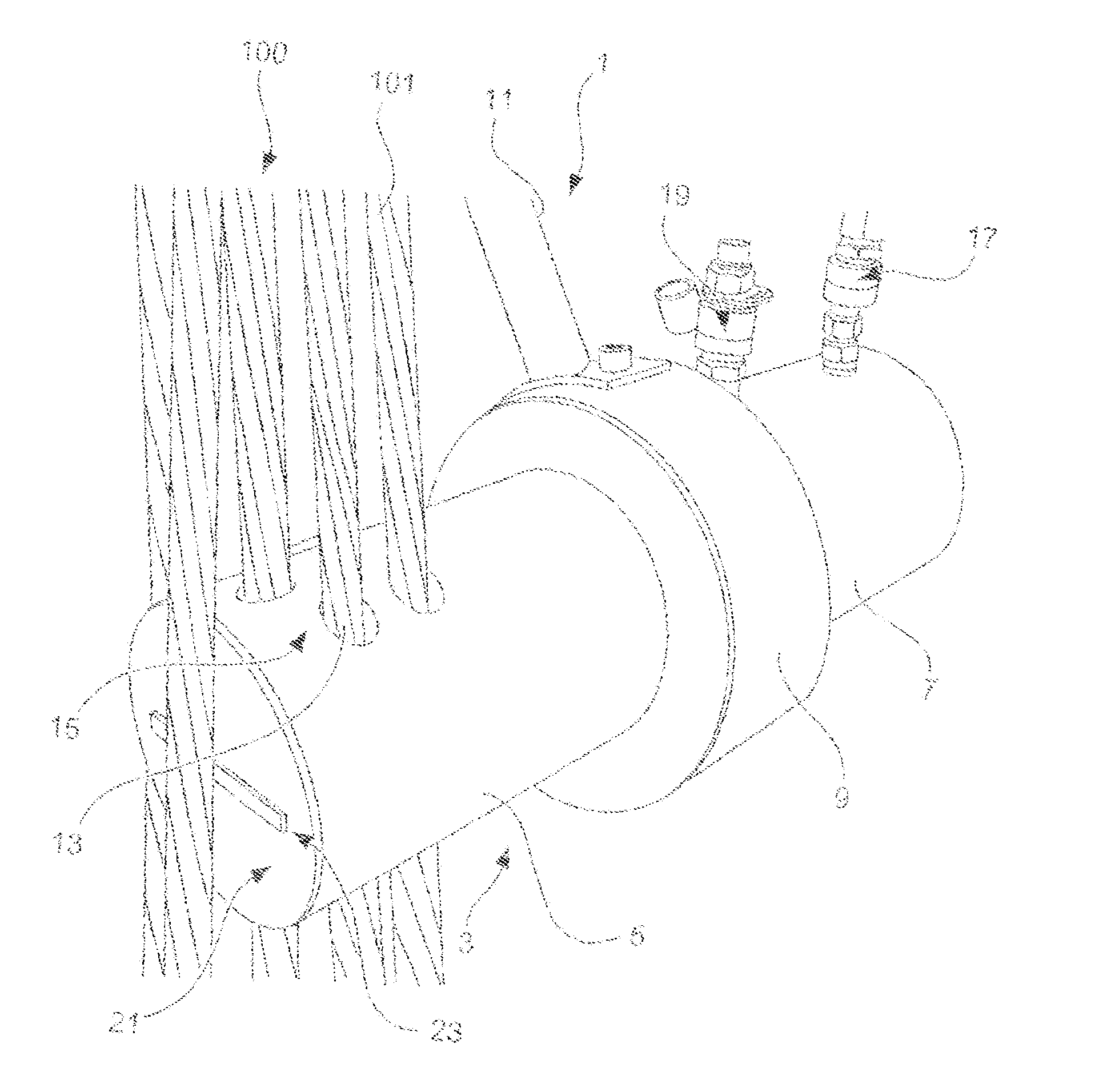
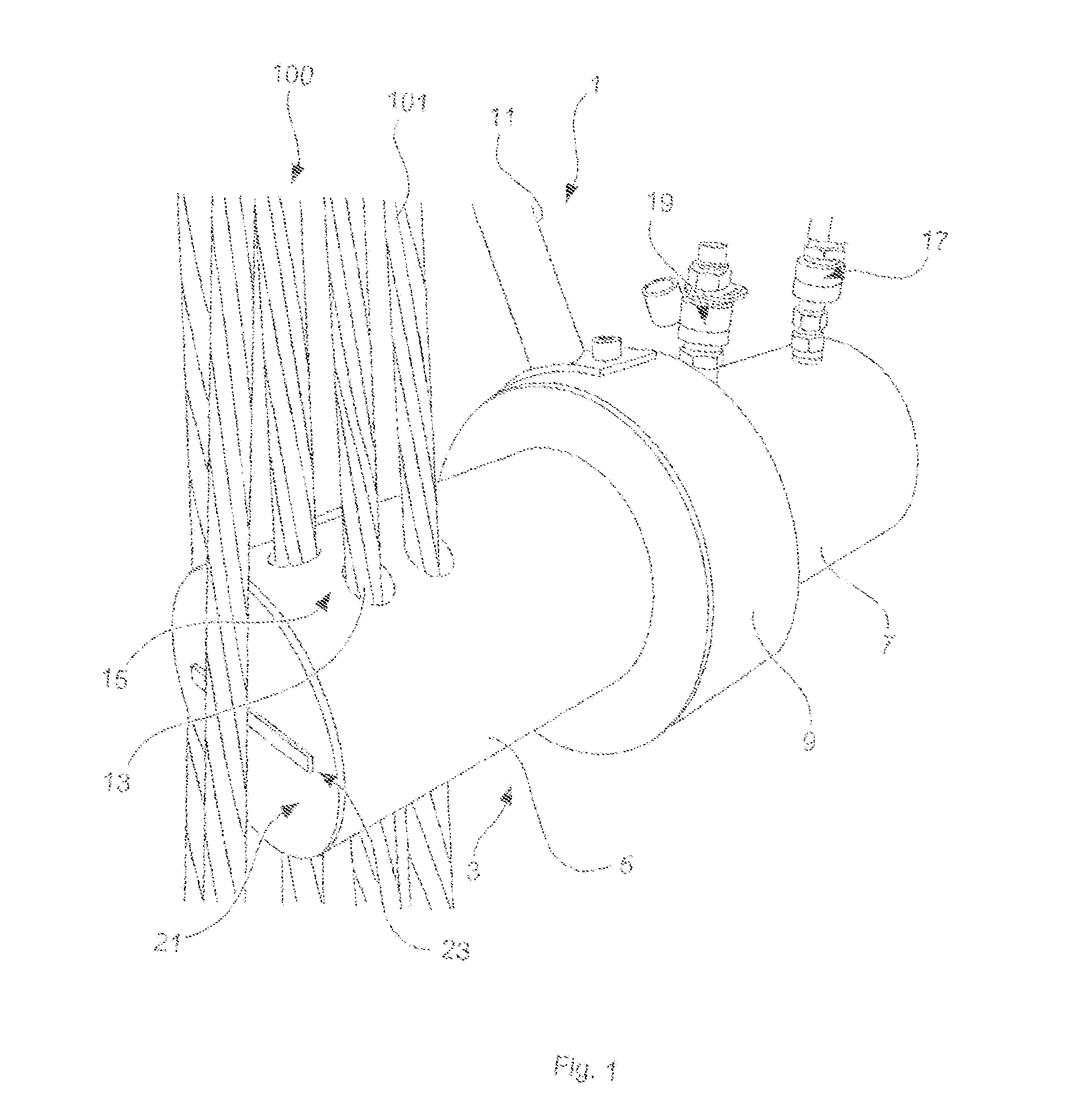
[0039]FIG. 1 shows a respective view of a stranded tensioning wire severing apparatus 1 according to one embodiment of the invention. The stranded tensioning wire severing apparatus 1 has a housing 3. The housing 3 has a first portion 5 and a second portion 7. The first portion 5 of the housing 3 is connected to the second portion 7 of the housing 3 by means of a union nut 9. The union nut 9 has a plurality of handles (one is shown) 11.

[0040]The first portion 5 of the housing 3 has a pattern 15 comprising a plurality of passage openings 13. A stranded tensioning wire 101 of a bundle 100 of stranded tensioning wires is passed into and through each of the passage openings 13 (for the sake of clarity only one is provided with...


PUM

PropertyMeasurementUnit
angleaaaaaaaaaa
angleaaaaaaaaaa
diameteraaaaaaaaaa

Abstract

One or more embodiments concerns a stranded tensioning wire severing apparatus for stranded tensioning wires of steel, in particular stranded tensioning wires of prestressed concrete structures such as for example pylons of wind power installations, which is adapted to sever a bundle comprising a plurality of stranded tensioning wires in one working operation.
One embodiment proposes that the apparatus has a housing, a cutting body arranged within the housing, and a plurality of passage openings corresponding to the plurality of stranded tensioning wires, which extend through the housing, wherein the passage openings are each penetrated by a slot adapted to receive the cutting body, and the cutting body has one or more cutting edges and is drivable in the housing movably in a cutting direction relative to the passage openings in such a way that the cutting edge or edges completely transit through the passage openings.

Description

BACKGROUND[0001]1. Technical Field[0002]The present invention concerns a stranded tensioning wire severing apparatus for stranded tensioning wires of steel, in particular stranded tensioning wires of prestressed concrete structures such as for example pylons of wind power installations, which is adapted to sever a bundle comprising a plurality of stranded tensioning wires in one working operation.[0003]2. Description of the Related Art[0004]For reinforcing prestressed concrete structures, in particular in the field of prestressed concrete pylons, use is made of stranded tensioning wires which by applying a tensile force provide for tensioning and overall reinforcement of the building structure. Taking the example of wind power installations, those stranded tensioning wires are fixedly connected in the tensioned condition to the structure. In the case of wind power installations the fixed connection is achieved for example by the stranded tensioning wires being anchored to the founda...

Claims


Application Information

Patent Timeline
Patent Type & Authority Applications(United States)
IPC IPC(8): B23D29/00
CPCB23D29/002B23D15/04B23D15/14B21F11/00B23D29/00
Inventor GOPFERT, HEINRICHGRAF, CHRISTOPH
Owner WOBBEN PROPERTIES GMBH
Why Eureka
Try Eureka