Industrial Robot Arm

a robot arm and industrial technology, applied in the field of robot arms, can solve the problems of inability to adapt the behavior of the arm to a specific environment, inability to control the arm, and more complicated and less reliable systems

Inactive Publication Date: 2015-10-08
DALAKIAN SERGEI
View PDF6 Cites 18 Cited by
  • Summary
  • Abstract
  • Description
  • Claims
  • Application Information

AI Technical Summary

Benefits of technology

[0014]The arm can include the secondary arm folding apparatus, similar to the main arm fold

Problems solved by technology

The main disadvantage of these arms—the section-mounted drives are located at a distance from its base.
Even in space applications, where weight is not an issue, a massive drives spinning around remote axle cause the inertia problems.
A much more complicated wire harnesses also make the system more complicated and less reliable.
That approach allows mounting o

Method used


Image

  • Industrial Robot Arm
  • Industrial Robot Arm
  • Industrial Robot Arm

Examples


Embodiment Construction

[0025]While the invention will be described in connection with one or more preferred embodiments, it will be understood that the invention is not limited to those embodiments. On the contrary, the invention includes all alternatives, modifications and equivalents as may be included within the spirit and scope of the appended claims. Like or corresponding parts of the respective views are indicated by like reference characters.

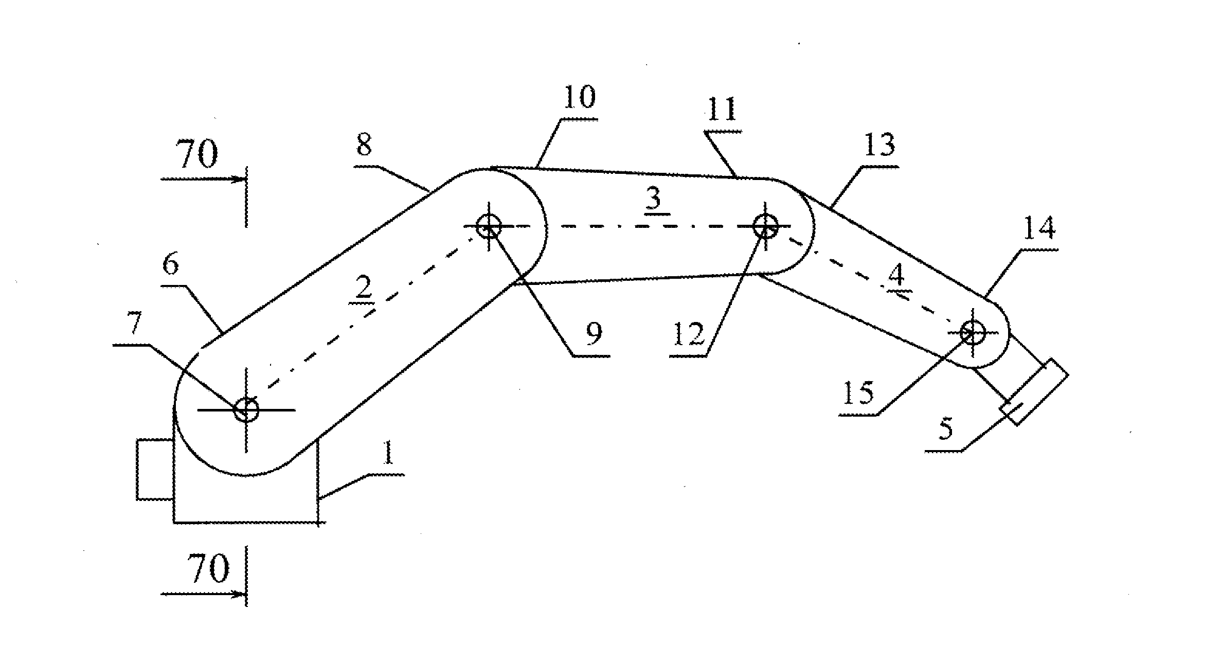
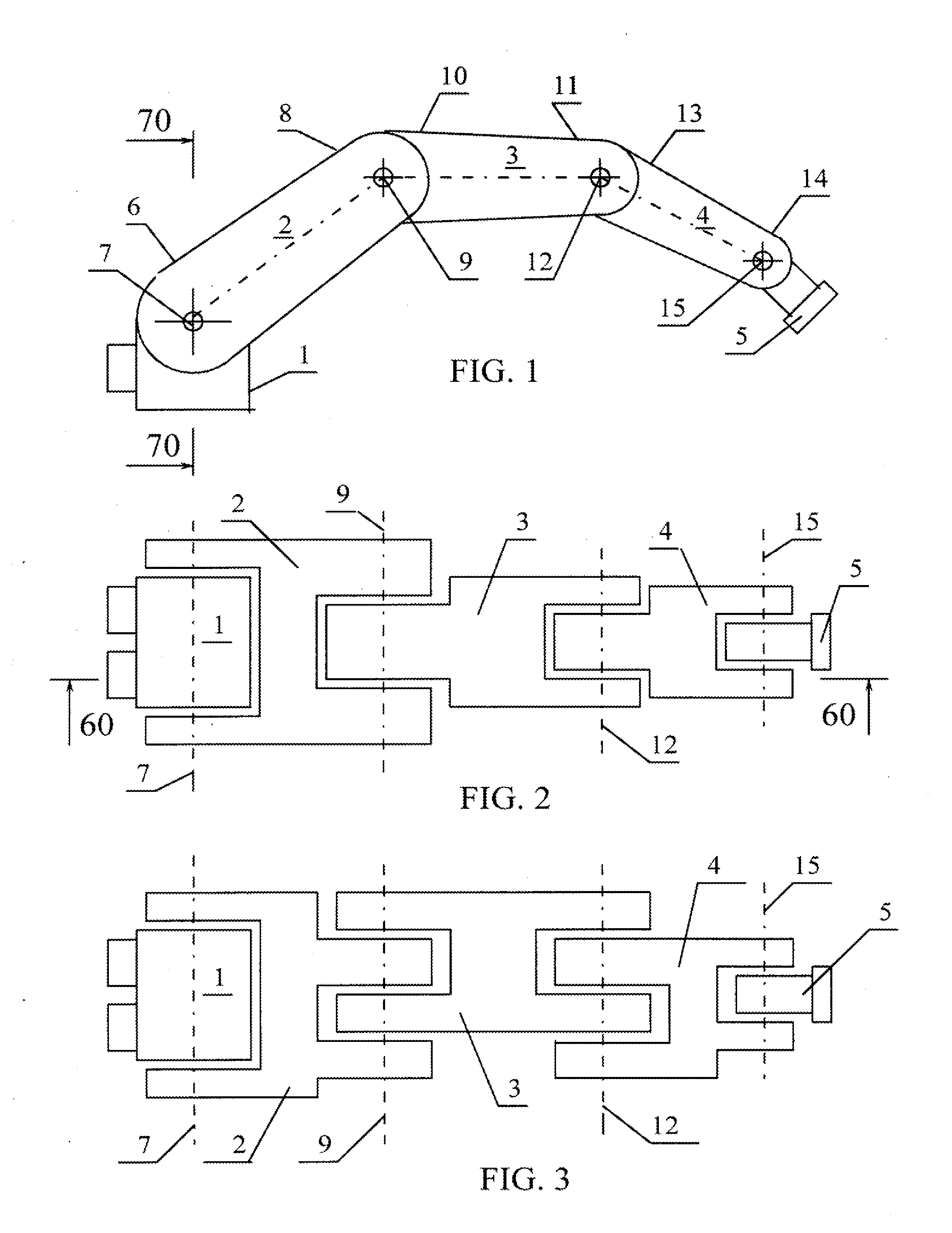
[0026]Referring now the drawings and particularly the FIG. 1 and FIG. 2, the robot arm comprises a base 1, an upper section 2, a middle section 3, a lower section 4 and final section 5. The upper section 2 has a first end 6 secured to the base 1 by a shoulder pivot 7 for rotation about a horizontal axis to define a shoulder joint permitting rotation of the upper section 2 in a vertical plane. If any additional movement of the robotic arm is also desired, the base 1 can be positioned on a turret or other apparatus allowing such movement.

[0027]The second end 8 of...


PUM


Abstract

An articulated robot arm or the like comprising a base, an upper section which is pivotally secured to the base at a shoulder joint, one or more middle sections pivotally secured to the upper section at an elbow joint, a lower section pivotally secured to the middle section at an wrist joint and a final section pivotally secured to the lower section. A main arm folding apparatus comprising an upper timing linkage, one or more middle timing linkages and lower timing linkage. The first lead gear of the main arm folding apparatus is fixed to the main drive pivot coaxial with the shoulder joint, the last slave gear of the arm folding apparatus is fixed to the final section. None of the other sections is fixed to the arm folding apparatus. That allows the arm to adapt its shape while folding around an object thus distributing pressure along its surface. The integration of the supplementary arm folding apparatus, similar to the main arm folding apparatus and linking said final section with the supplemental drive pivot coaxial with said shoulder joint, allows implementation of the controlled stiffness via internal preloading of the arm. Each timing linkage could be implemented as a set of sprockets linked by chain (or timing belt) or gears linked via a parasite gear. Coordinated operation of a system comprising two or more robot arms allows manipulation of large fragile objects.

Description

BACKGROUND OF THE INVENTION[0001]The present invention related to robot arms, and particularly to articulated robot arms which are used industrially in automated manufacturing operations and the like.[0002]Articulated robot arms are used in industry to perform two major operations:[0003]Moving a tool along a desired trajectory (welding, cutting, painting);[0004]Manipulating object's position and orientation (placing objects on a conveyor in a certain orientation, assembling parts and the like).(Movements of all sections of an articulated arm must be coordinated with respect to each other in order to provide the desired movement of the final section.)[0005]Each section of an articulated arm must move in a well-defined way, in relation to the other sections of the arm. Such precision is required to move the terminal segment, or final section, of the arm in the directions and to the positions which are necessary to carry out the intended function.[0006]In most articulated arms each sec...

Claims


Application Information

Patent Timeline
IPC IPC(8): B25J17/02
CPCY10T74/20323B25J17/025B25J9/046B25J9/102B25J9/104
Inventor DALAKIAN, SERGEI
Owner DALAKIAN SERGEI
Why Eureka
Try Eureka