Liner sump dispensing system

a sump dispensing system and liner technology, applied in the field of bulk material liners, can solve the problems of large quantity of content remaining in the liner, difficult use of devices, and incomplete or near-complete evacuation of contents from within the liner

Active Publication Date: 2015-10-08
GRAYLING INDS
View PDF11 Cites 33 Cited by
  • Summary
  • Abstract
  • Description
  • Claims
  • Application Information

AI Technical Summary

Problems solved by technology

A problem long associated with the use of such liners has been the complete or near-complete evacuation of the contents from within the liner.
While these devices have aided in the evacuation of the liner they can still result in rather large quantities of content remaining within the liner.
These devices have proved to be difficult to use due to the massive weight of a filled liner.

Method used


Image

  • Liner sump dispensing system
  • Liner sump dispensing system
  • Liner sump dispensing system

Examples


Embodiment Construction

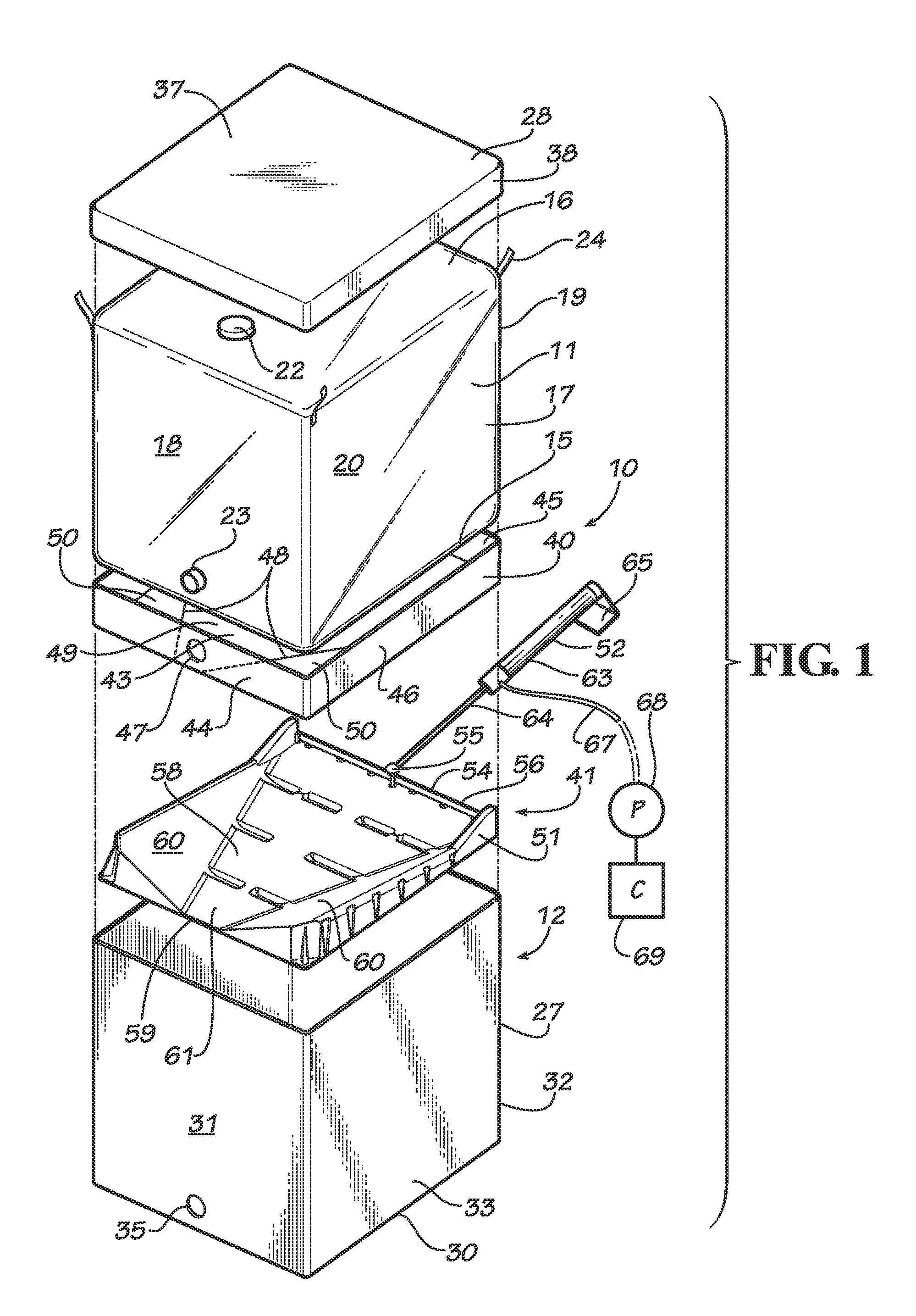
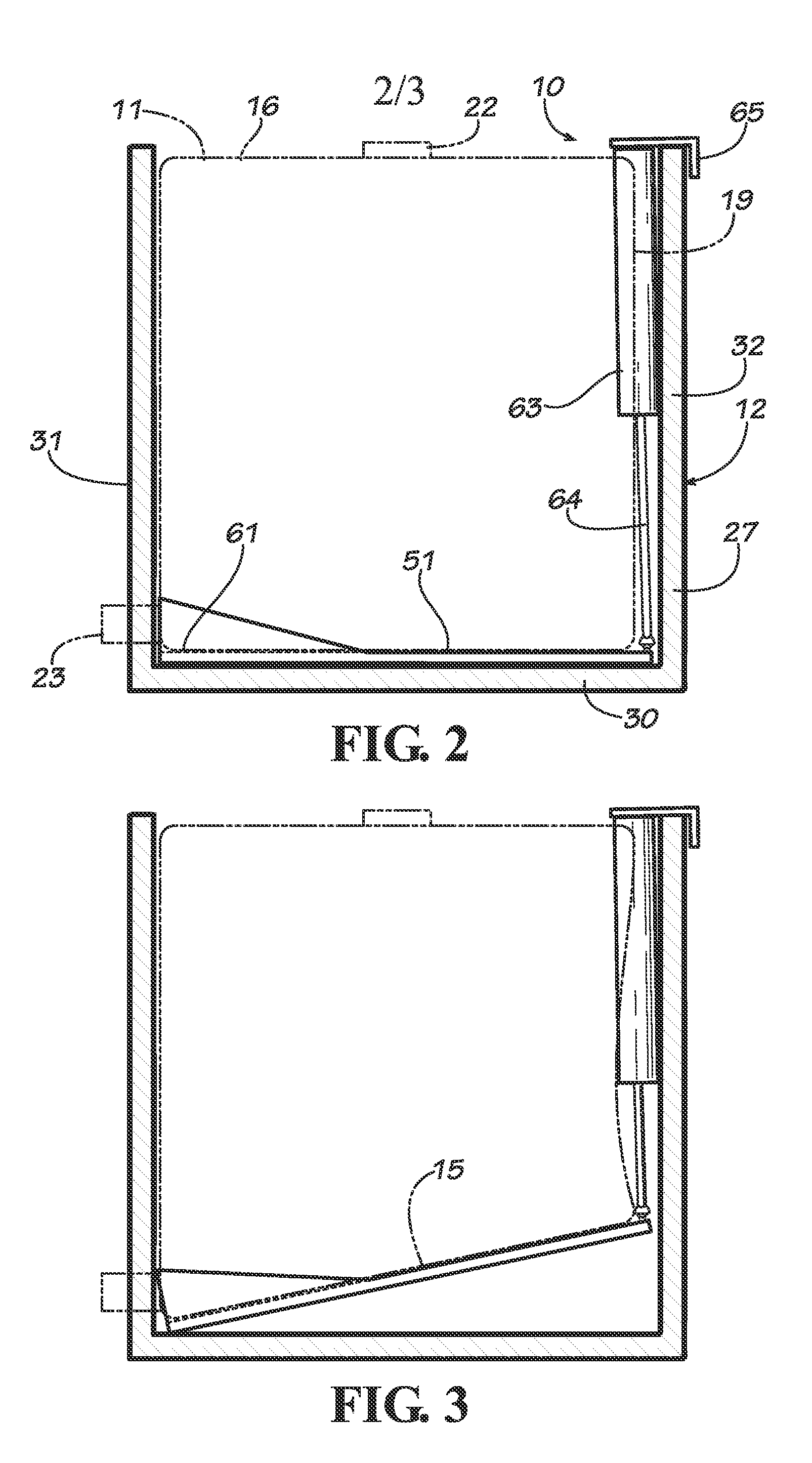
[0008]With reference next to the drawings, there is shown a liner sump dispensing system 10 embodying principles of the invention in a preferred form. The liner sump dispensing system liner 10 is configured to be used in conjunction with a conventional plastic film, flexible liner 11 and a conventional intermediate bulk container 12. The bulk container 12 is in the form of a generally rigid container made of a plastic, cardboard, or paper material.

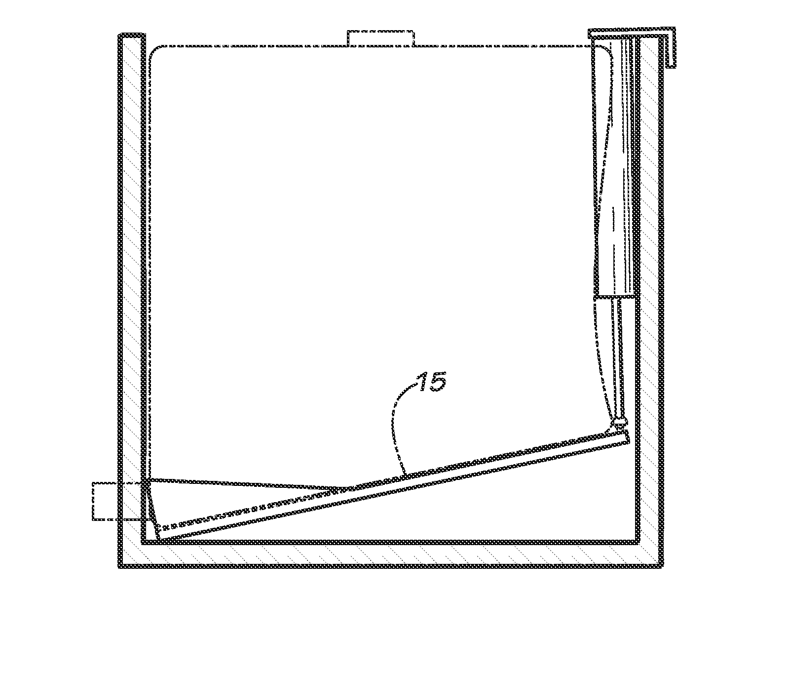
[0009]The liner 11 has the general configuration of a rectangular prism or cuboid, which may also be considered to be generally considered box-shaped. The liner 11 has a bottom wall 15, a top wall opposite the bottom wall 15, and four side walls 17 extending between the bottom wall 15 and top wall 16. The four side walls 17 include a front wall 18, a rear wall 19, and two oppositely disposed end walls 20. The top wall 16 includes a top opening fitment 22 through which bulk material or content may be passed through and into the liner. The f...


PUM


Abstract

A liner sump dispensing system (10) is disclosed which is used in conjunction with a liner (11) and an intermediate bulk container (12). The liner sump dispensing system includes a liner cassette (40) and a tilting device (41). The liner cassette is mounted to the bottom of the liner. The tilting device includes a tray (51) and a reciprocating pneumatic arm (52) having a pneumatic cylinder (63) and a piston rod (64) pivotally coupled to a rear end (54) of the tray. The tray has a trapezoidal shaped floor (58) and a pair of inclined wings (60) extending upwardly along an incline from the floor. A L-shaped mounting flange (65) adapted to be coupled to the top end of the container is coupled to the end of the pneumatic cylinder opposite from the tray. The actuation of the pneumatic cylinder tilts the tray to tilt the liner bottom end.

Description

TECHNICAL FIELD[0001]This invention relates to bulk material liners used in conjunction with bulk containers, and particularly to a sump dispensing system used in conjunction with intermediate bulk container liners.BACKGROUND OF THE INVENTION[0002]Flexible liners are oftentimes utilized in conjunction with an intermediate bulk container or bag to ship large quantities of liquid, viscous or granular products. A problem long associated with the use of such liners has been the complete or near-complete evacuation of the contents from within the liner. As such, some liners have included pressurized regions to lift or angle the bottom of the liner in order to move the contents closer to the outlet of the liner. While these devices have aided in the evacuation of the liner they can still result in rather large quantities of content remaining within the liner.[0003]Devices have also been used to lift or tilt the liner to aid in the dispensement of the contents. These devices may tilt the e...

Claims


Application Information

Patent Timeline
Patent Type & Authority Applications(United States)
IPC IPC(8): B65D88/60B65D88/56
CPCB65D88/56B65D88/60B65D77/061B65D2231/008
Inventor SULLINGER, RANDY R.MCKEE, TONY R.
Owner GRAYLING INDS
Why Eureka
Try Eureka