Unidirectional clutch device

Inactive Publication Date: 2015-10-08
FLYER CO LTD
View PDF6 Cites 15 Cited by
  • Summary
  • Abstract
  • Description
  • Claims
  • Application Information

AI Technical Summary

Benefits of technology

[0009]The main objective of the invention is to provide a unidirectional clutch device having a si

Problems solved by technology

However, the conventional unidirectional clutch device has a complicated structure and is laborious in assembling.
The clutch blocks 60 are also easily worn off, and the useful life of the clutch devic

Method used


Image

  • Unidirectional clutch device
  • Unidirectional clutch device
  • Unidirectional clutch device

Examples


Example

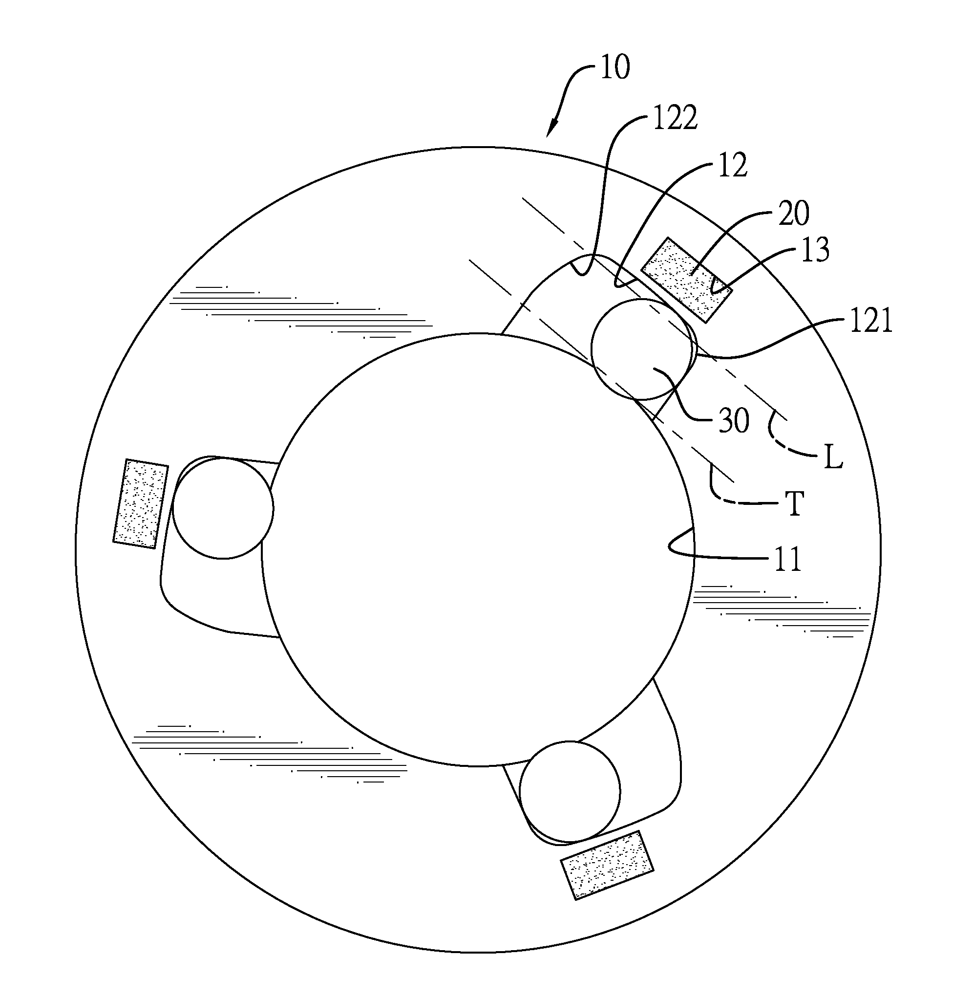
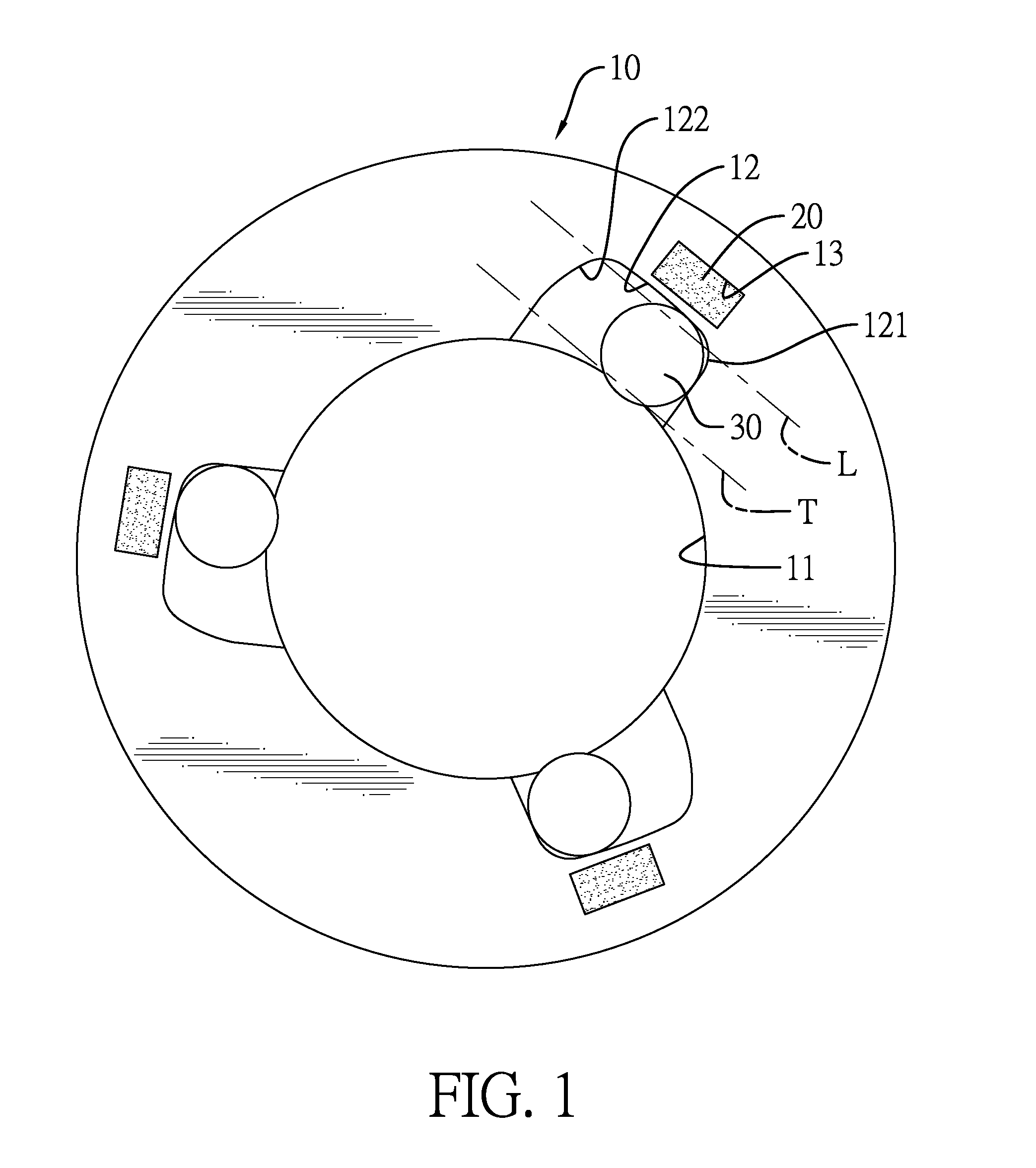
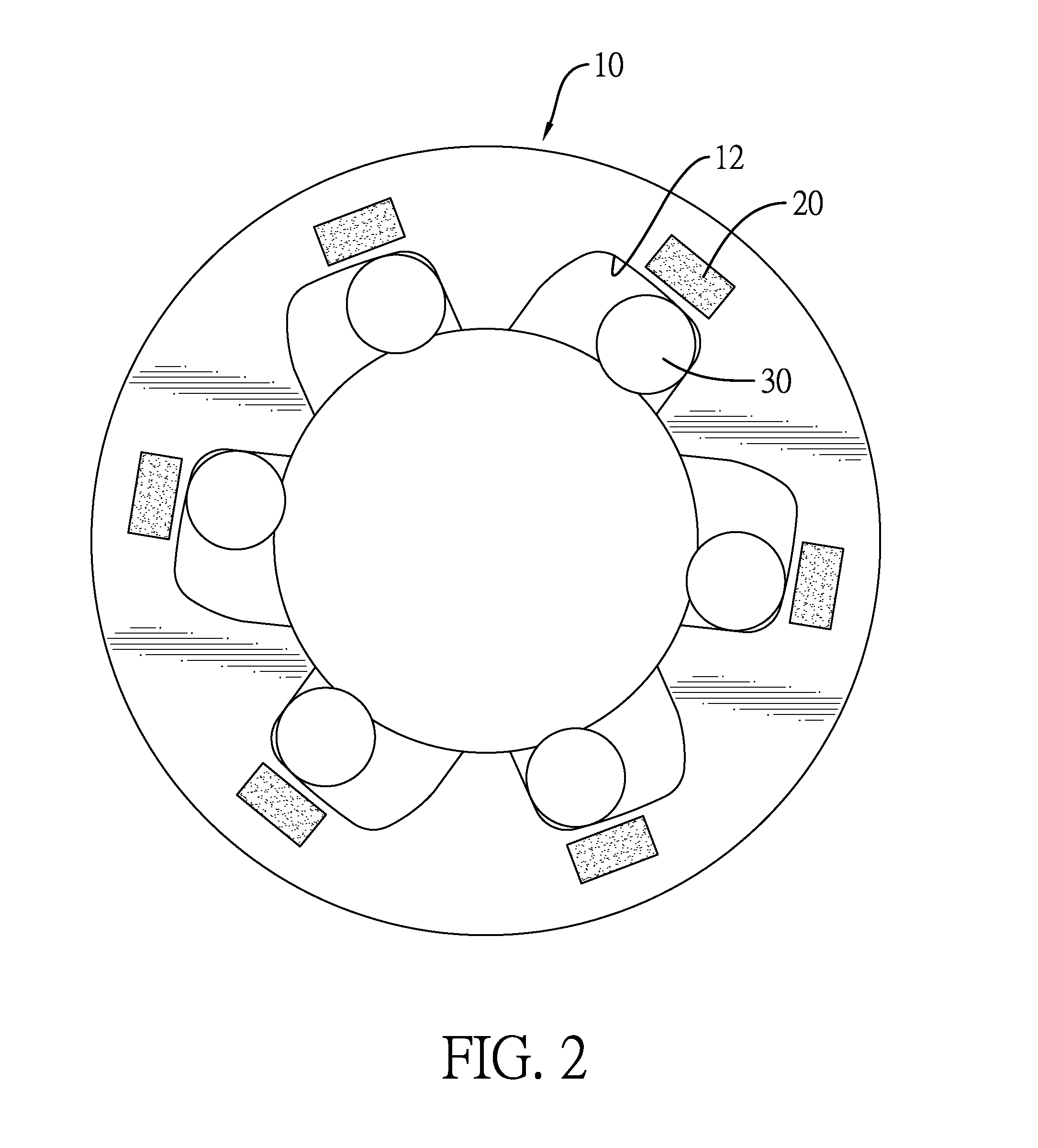
[0020]With reference to FIG. 1, a unidirectional clutch device in accordance with the present invention comprises a driving board 10, multiple permanent magnets 20, and multiple clutching elements 30.

[0021]The driving board 10 may be a round disk, is made of a non-magnetic material, and comprises an axle hole 11, multiple holding recesses 12, and multiple magnet recesses 13. The axle hole 11 is defined axially through the driving board 10. The holding recesses 12 are defined in the driving board 10 and are arranged around and communicate with the axle hole 11, and each holding recess 12 has a mouth and an inclined radial bottom. The mouth communicates with the axle hole 11. The radial bottom is away from and opposite the mouth and is inclined relative to a line L that is parallel with a tangent line T of the axle hole 11 to form a long end 122 and a narrow end 121 respectively on two ends of the holding recess 12. The long end 122 of the holding recess 12 has a radial width longer t...


PUM


Abstract

A unidirectional clutch device has a driving board, multiple permanent magnets, and multiple clutching elements. The driving board has an axle hole and multiple holding recesses. The holding recesses are defined in the driving board and are arranged around and communicate with the axle hole. Each holding recess has a long end having a radial width and a narrow end having a radial width smaller than that of the long end. The permanent magnets are mounted on the driving board and are located at positions adjacent to the narrow ends of the holding recesses. The clutching elements are rotatably mounted respectively in the holding recesses and are made of a magnetically conductive material. Each clutching element is moveable in a corresponding one of the holding recesses toward the narrow end of the corresponding holding recess by an attraction of a corresponding one of the permanent magnets.

Description

BACKGROUND OF THE INVENTION[0001]1. Field of the Invention[0002]The present invention relates to a clutch device, and more particularly to a unidirectional clutch device that is applied to an actuating device of a vehicle.[0003]2. Description of Related Art[0004]A unidirectional clutch device is usually applied to an actuating device of a vehicle. With reference to FIG. 8, a conventional clutch device comprises a round driving board 50, multiple clutch blocks 60, multiple springs 62, and multiple pushing blocks 61. The driving board 50 has an axle hole 51, multiple holding recesses 52, and multiple spring holes 53. The axle hole 51 is axially defined through the driving board 50. The holding recesses 52 are defined in the driving board 50 and are arranged around and communicate with the axle hole 51, and the clutch blocks 60 are mounted respectively in the holding recesses 52. The spring holes 53 are defined inclinedly in the periphery of the driving board 50, and each spring hole 5...

Claims


Application Information

Patent Timeline
IPC IPC(8): F16D41/066F16D27/01
CPCF16D27/01F16D41/066F16D2041/0665
Inventor LIN, YU-TSAI
Owner FLYER CO LTD
Why Eureka
Try Eureka