System and method for tracking guiding lines by an autonomous vehicle

a technology of autonomous vehicles and tracking lines, applied in the direction of distance measurement, process and machine control, instruments, etc., can solve the problems of requiring a higher level of accuracy, requiring less accuracy, and requiring a fast moving transporting means to drill a groove in an existing floor in order to bury rf transmitting wires along the travel path

Active Publication Date: 2015-10-08
UNITRONICS AUTOMATED SOLUTIONS
View PDF13 Cites 27 Cited by
  • Summary
  • Abstract
  • Description
  • Claims
  • Application Information

AI Technical Summary

Benefits of technology

[0010]An autonomous transporting tool (TT) is disclosed adapted to travel along a guiding line, the TT comprising a first and a second transporting tool element (TTE). Each of the TTEs comprises an autonomous propulsion means, a control system and an optical system comprising two cameras and two lighting units, wherein a first camera and a first lighting unit are located proximal to a first end of said transporting tool element and said second camera and said second lighting unit are located proximal to a second end of said transporting tool element, and wherein said first and second lighting units are direct to illuminate the field of view each of its respective camera. The system further comprises steering means to allow directing of said transporting tool element to directions between a rightmost and a leftmost steering angle, wherein communication means communicate at least with each other, wherein said first and second transporting tool elements are mechanically disengaged, and wherein said first and second transporting tool elements are adapted to communicate with each other via wireless communication channel to manage and control the distance between them and coordinate movements of the first and second tool elements. In the disclosed transporting system, at least one of said first and said second transporting tool elements further comprises distance measuring sensor adapted to measure the distance between said first and said second transporting tool elements.
[0011]A system is further disclosed for guiding at least one autonomous transporting tool (TT) adapted to travel along a guiding line comprising, the system comprising at least one autonomous transporting tool (TT). The TT comprises a first and a second transporting tool elements (TTE), wherein each of said transporting tool elements comprises an autonomous propulsion means, a control system and an optical system comprising two cameras and two lighting units, wherein a first ...

Problems solved by technology

However, this method requires installations that involve either placement of the RF wires during the installation of the respective parking floor or entering the wire into an existing floor.
However, drilling of grooves in an existing floor in order to bury RF transmitting wires along the travel paths may be not only very expensive and time-consuming, but may also require careful work in order not to damage other under-surface installations and in order to avoid risk of damaging constructive elements while performing the grooves.
Accordingly, slow moving transporting means may allow for less accuracy, while fast moving transporting means may require higher level of accuracy due to lower tolerance for inaccuracy of placement of the vehicle on the transporting means due to higher mechanical forces acting on the carried vehicle during maneuvering of the transporting means.
Addressing the l...

Method used


Image

  • System and method for tracking guiding lines by an autonomous vehicle
  • System and method for tracking guiding lines by an autonomous vehicle
  • System and method for tracking guiding lines by an autonomous vehicle

Examples


Embodiment Construction

[0027]In the following detailed description, numerous specific details are set forth in order to provide a thorough understanding of the invention. However, it will be understood by those skilled in the art that the present invention may be practiced without these specific details. In other instances, well-known methods, procedures, and components have not been described in detail so as not to obscure the present invention.

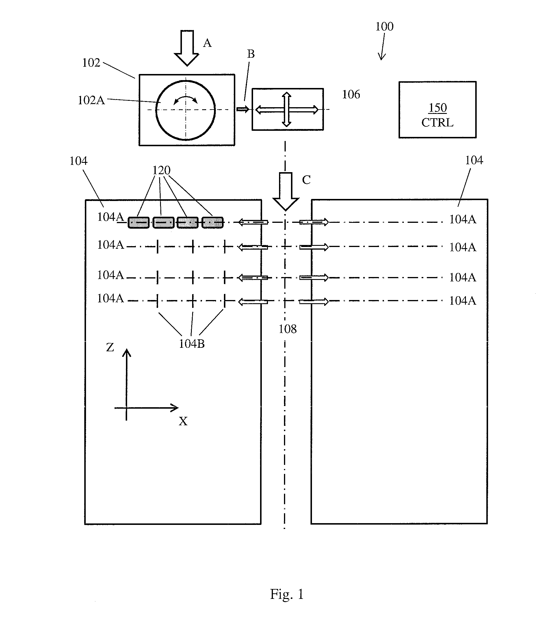
[0028]FIG. 1, to which reference is made now, schematically presents typical automated parking space 100. Parking space 100 comprises parking in / out unit 102, transport direction changer 106, and parking area(s) 104 each having a plurality of parking lines 104A and longitudinal traveling path 108. Parking space may have a plurality cars 120 parked in it along parking lines 104A. Parking in / out unit 102 may be adapted to accommodate an incoming vehicle driving into it substantially along arrow A. When the specific conditions in parking space 100 require, parking in...


PUM


Abstract

An autonomous transporting tool is adapted to travel along a guiding line. The tool comprises two transporting elements. Each of the transporting elements comprise autonomous propulsion means, a control system and an optical system. The optical system comprises two cameras and two lighting units. The system is adapted to identify the location of the image of a guiding line within a received image of the floor and to provide steering commands adapted to steer the transporting tool so that the image of the guiding line is located substantially in the center of the received image.

Description

BACKGROUND OF THE INVENTION[0001]Automated parking systems are known in the art for many years. One of their goals is to increase the number of parked vehicles in a given parking space, either having a single story or multi-story facility. Converting of an existing traditional parking space into an automated parking space requires, among others, installation and operation of location and navigation means that will enable automated mobile means to load an incoming vehicle at a loading position and transport it to an intended parking area at the beginning of the parking period and to pick a parking vehicle from a given parking space and move it to an exit location at the end of the parking period, as well as enable the automated system to transport a parked vehicle from its current parking area to another, pre-defined parking area.[0002]According to solutions known in the art, elements of the automated parking system that travel through the parking space are directed along route guidi...

Claims


Application Information

Patent Timeline
IPC IPC(8): G05D1/02B65G1/137E04H6/22G05D1/00
CPCG05D1/0246E04H6/22B65G1/137G05D1/0022E04H6/36B60B30/02B60B30/10G05D1/0234G05D2201/0216E04H6/305B62B5/0083E04H6/24
Inventor SHANI, HAIM
Owner UNITRONICS AUTOMATED SOLUTIONS
Why Eureka
Try Eureka