Screw element for use in spinal, orthopedic or trauma surgery and a system of such a screw element and a screw driver adapted thereto

Active Publication Date: 2015-10-15
BIEDERMANN TECH GMBH & CO KG
View PDF50 Cites 6 Cited by
  • Summary
  • Abstract
  • Description
  • Claims
  • Application Information

AI Technical Summary

Benefits of technology

[0007]It is the object of the invention to provide a screw element and a system of a screw element and a correspondin

Problems solved by technology

With the known screw elements and drivers there might sometimes be a problem to locate the drive portion of the screw

Method used


Image

  • Screw element for use in spinal, orthopedic or trauma surgery and a system of such a screw element and a screw driver adapted thereto
  • Screw element for use in spinal, orthopedic or trauma surgery and a system of such a screw element and a screw driver adapted thereto
  • Screw element for use in spinal, orthopedic or trauma surgery and a system of such a screw element and a screw driver adapted thereto

Examples


first embodiment

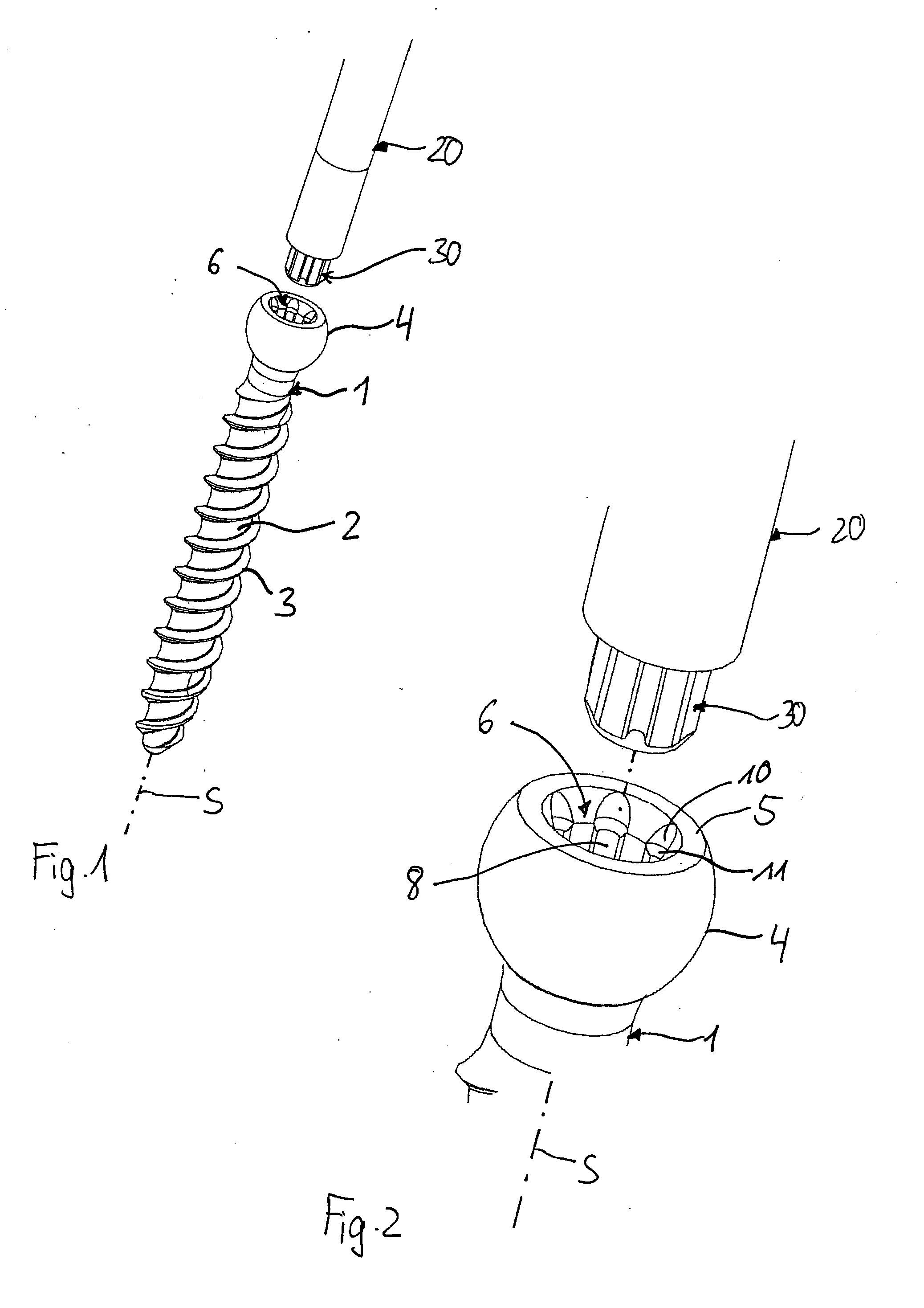
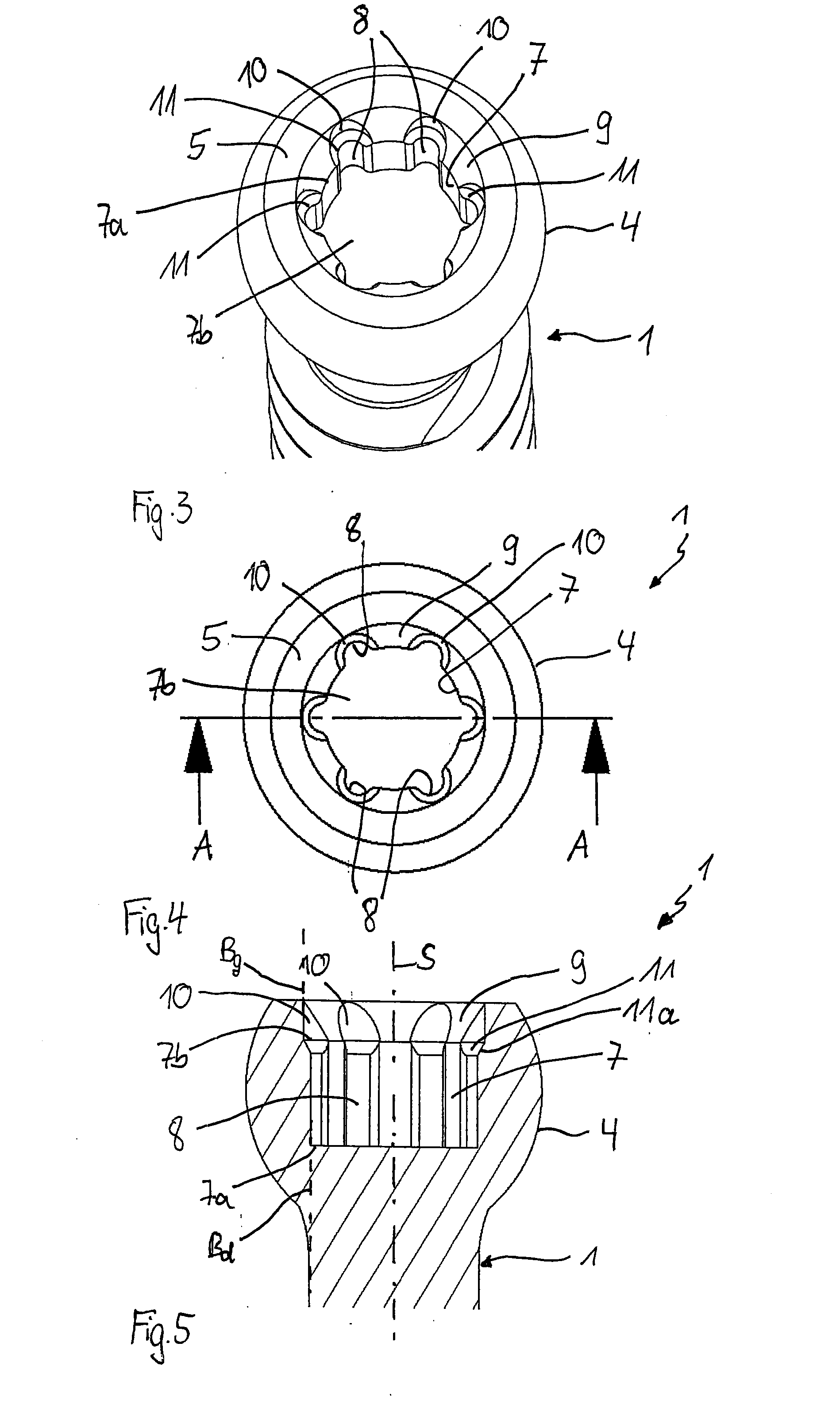
[0025]Referring to FIGS. 1 to 5, a screw element 1 comprises a shank 2 with a bone thread 3 in at least a portion of the shank 2 and a head 4. The shank 2 is configured to be inserted into a bone or in particular into a pedicle of a vertebra. A screw axis S is defined by the axis of the bone thread 3. The head 4 has the shape of a segment of a sphere and a free end 5 on a side that is opposite to the shank 2. The bone thread 3 defines a screw axis S. At the free end 5, a drive portion 6 that is configured to be engaged with an engagement portion of a driver is provided. The drive portion 6 will be explained more in detail below.

[0026]A system of the screw element 1 with the drive portion 6 and a screw driver includes a screw driver 20 that has an engagement portion 30 adapted for engagement with the drive portion 6 of the screw element 1.

[0027]As depicted in particular in FIGS. 3 to 5, the drive portion 6 of the screw element 1 comprises a first recess 7 that is located at a distan...

second embodiment

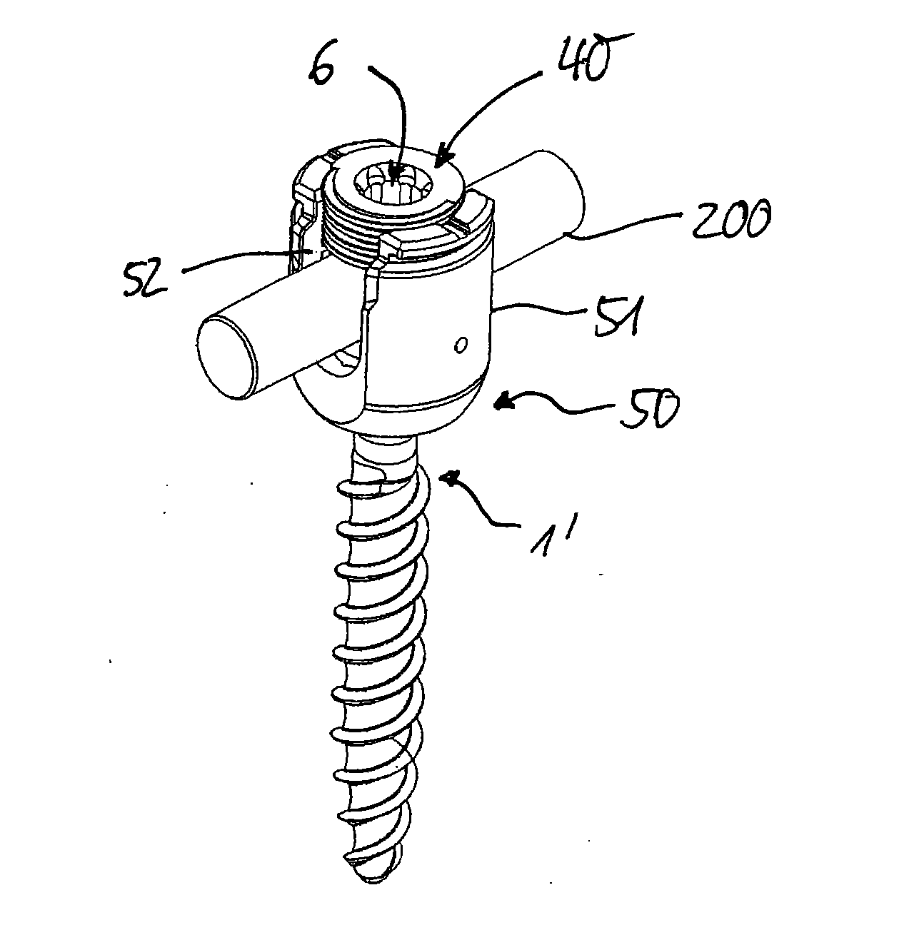
[0036]a screw element will be explained with reference to FIG. 12. Parts and portions that are identical to the previous embodiments have the same reference numerals and the description thereof is not repeated. In this embodiment, the screw element is a set screw 40 that is used in a polyaxial bone anchoring device 50. The polyaxial bone anchoring device 50 is shown only in an exemplary manner, many different designs of such polyaxial bone anchoring device may be contemplated. The polyaxial bone anchoring device 50 comprises a screw element 1′ that has a spherical segment-shaped head (not shown) and that may have a known drive portion, such as, for example, a known torx-shaped drive portion or a polygon-shaped drive portion or that may have also a drive portion 6 according to the previous embodiments. The screw element 1′ is pivotably connected to a receiving part 51 that comprises a seat to hold the head of the screw element in a ball and socket manner. A pressure element (not show...


PUM


Abstract

A screw element for use in spinal, orthopedic or trauma surgery, the screw element including a screw axis (S) and a screw thread (3); a drive portion (6) for engagement with a screw driver (20), wherein the drive portion (6) comprises a first recess (7) with a wall and substantially longitudinally extending drive grooves (8) formed in the wall, a second recess (9) between a free end (5) of the screw element (1, 1′) and the first recess (7), wherein the second recess (9) has a wall and a gradually increasing inner diameter towards the free end (5); and wherein in the wall of the second recess (9) guide grooves (10) are formed at positions corresponding to the position of the drive grooves (8) that allow an engagement portion (30) of a screw driver to be guided to enter the drive grooves (8). Further, a system is provided that includes the screw element and a screw driver adapted thereto.

Description

CROSS-REFERENCE TO RELATED APPLICATIONS[0001]The present disclosure claims benefit of the U.S. Provisional Patent Application Ser. No. 61 / 979,818, filed on Apr. 15, 2014, the contents of which are hereby incorporated by reference in their entirety, and claims priority from European Patent Application EP 14164692.7, filed on Apr. 15, 2014, the contents of which are hereby incorporated by reference if their entirety.BACKGROUND[0002]1. Field of the Invention[0003]The invention relates to a screw element for use in spinal, orthopedic or trauma surgery and to a screw driver adapted to the screw element. The screw element includes a drive portion for engagement with a screw driver wherein the drive portion comprises drive grooves for engagement with corresponding engagement protrusions of the screw driver and guide grooves that are configured to guide the engagement protrusions of the screw driver into the drive grooves. The screw element can be used in particular in minimally invasive su...

Claims


Application Information

Patent Timeline
IPC IPC(8): A61B17/70
CPCA61B17/7002A61B17/7082A61B17/7059A61B17/8615A61B17/8888A61B17/888
Inventor BIEDERMANN, LUTZDANDANOPOULOS, DIMOSTHENISMATTHIS, WILFRIED
Owner BIEDERMANN TECH GMBH & CO KG
Why Eureka
Try Eureka