Eureka AIR delivers breakthrough ideas for toughest innovation challenges, trusted by R&D personnel around the world.

Lead-based protective shielding system

Inactive Publication Date: 2015-10-15
PB LAMINATIONS & SPECIALTY SUPPLY
View PDF3 Cites 2 Cited by
  • Summary
  • Abstract
  • Description
  • Claims
  • Application Information

AI Technical Summary

Benefits of technology

The device described in this patent helps prevent the leakage of radiation (like X-rays or gamma rays) through walls and screw holes in lead-shielded structures. It consists of a thin lead strip that is securely held in place by a holder attached to a metal C stud. The lead strip blocks the radiation from leaking through the wall joint or screw holes. The device can be placed horizontally or vertically to address different needs. It is made up of a metal C stud and a thin lead strip that is attached to the stud using clips and an extension piece. The lead strip holder is secured to the extension piece using a clip, ensuring stability and effectiveness. Overall, this device helps create a safe and secure environment for research and medical facilities.

Problems solved by technology

However, conventional methods for installing lead-based protective shielding to walls are time consuming and / or wasteful.
Lead plugs and batten strips become difficult to use when lead thickness is greater than about an eighth of an inch.
However, installing angled lead plates can be very difficult.
Additionally, angled lead plates often block access for wiring and plumbing in the wall.

Method used


Image

  • Lead-based protective shielding system
  • Lead-based protective shielding system
  • Lead-based protective shielding system

Examples


Embodiment Construction

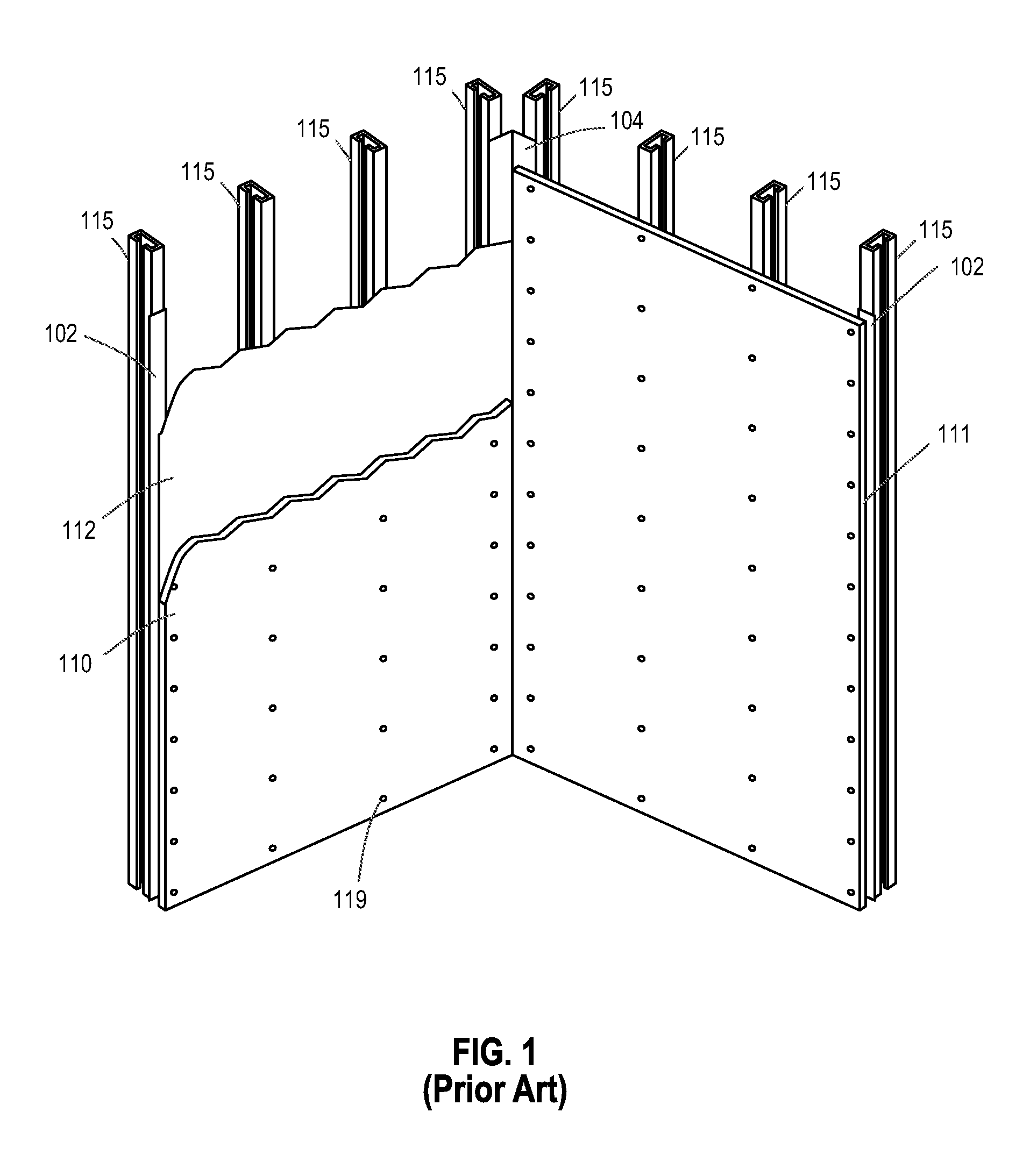
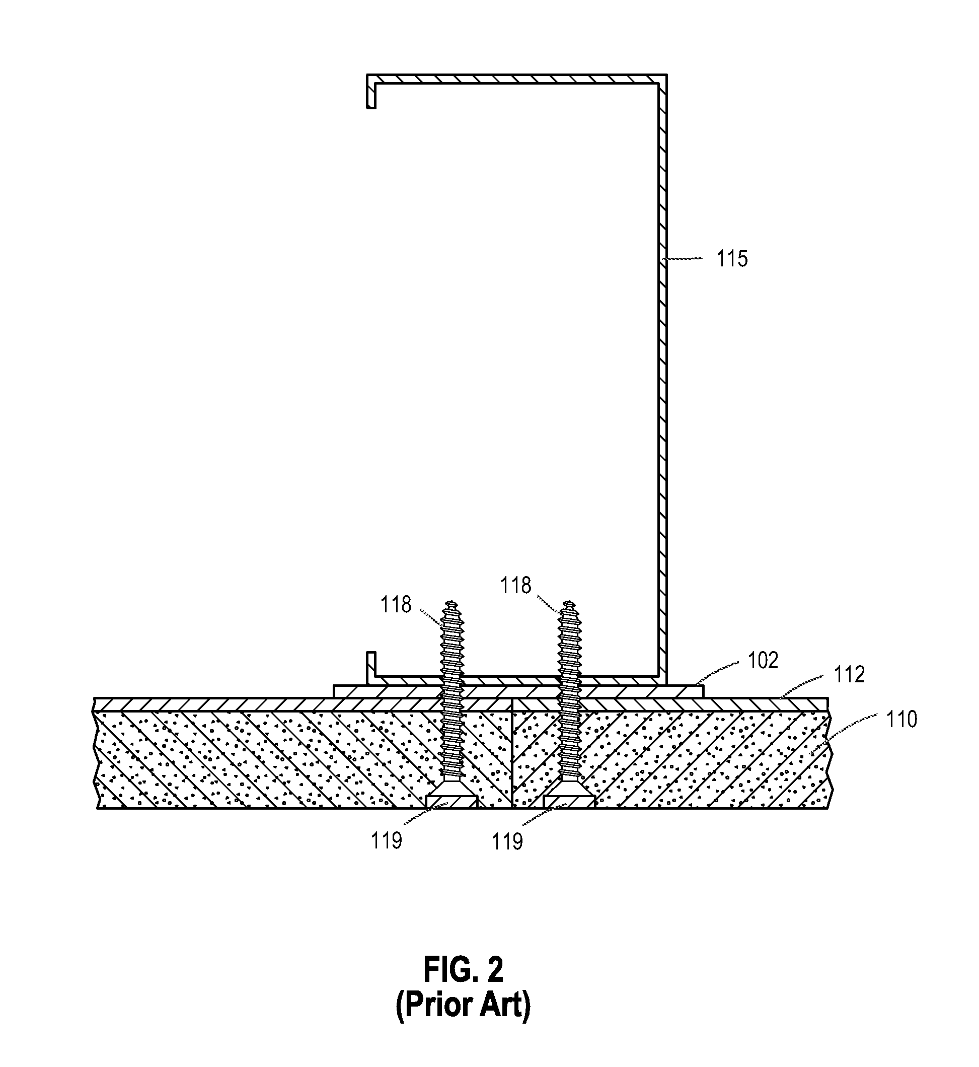
[0018]Referring to FIG. 1, a prior art installation of a lead-based protective shielding system to framed walls is illustrated. As shown, each wall section is constructed with a lead-lined gypsum wallboard (drywall) 111. The lead-lined gypsum wallboard 111 includes gypsum wallboard 110 glued on the back side to a lead sheet 112. The gypsum wall board 111 can be 48 inches in width and from eight to twelve feet in height, for example. It is recommended that the lead-lined gypsum wallboard 111 be fastened at a minimum of 8″ on center at the edges of each sheet, and at a minimum of 12″ on center at the intermediate studs with drywall screws. To avoid radiation leakage, additional measures are taken. For example, thin (e.g., 2″ in width) batten lead strips 102 can be installed over each of the vertical wall joints and lead corner ribbons 104 are installed at the corners. Additionally, the installer must countersink drywall screws 118 into the lead-laminated gypsum board 111 (as illustrat...


PUM


Abstract

A device useful to block radiation (e.g., X-ray, gamma ray) leakage through a wall joint and screw holes in a lead-shielded structure is provided. The device includes a substantially planar lead strip which is at least the thickness of the lead sheeting covering the structure, and a lead strip holder adapted to hold the lead strip securely in place and attach the lead strip to a metal C stud such that when attached thereto, the lead strip forms a barrier which blocks radiation leaking through the wall joint and adjacent screw holes. Clips can be used to attach the lead strip holder to the stud, wherein each of the clips includes a U-shaped portion to frictionally fit onto a U-shaped portion of the lead strip holder. In various embodiments, the device can be used on vertical or horizontal wall joints.

Description

BACKGROUND OF THE INVENTION[0001]1. Field of the Invention[0002]The present invention relates to lead-based protective shielding systems.[0003]2. Description of the Related Art[0004]The most important property of a shielding material for use in countering the effects of X-ray and gamma rays is the density of the material. Although lead is not the densest element, lead is readily available and has the lowest cost of the higher density materials. It is also relatively easy to work with and is resistant to contamination from dirt and other materials.[0005]Lead shielding in the form of lead sheets or plates is widely used in hospitals, laboratories and industrial facilities. For example, the walls of a typical X-ray room are surrounded with lead sheeting to prevent radiation leakage. Such lead sheeting requires adequate support, so the lead sheets are usually attached to a substrate such as plywood or gypsum board.[0006]However, conventional methods for installing lead-based protective ...

Claims


Application Information

Patent Timeline
IPC IPC(8): E04B1/92G21F1/08
CPCE04B1/92E04B2103/06E04B2001/925G21F1/085E04B2/7457G21F3/00
Inventor SIMSON, GARY A.
Owner PB LAMINATIONS & SPECIALTY SUPPLY
Why Eureka
Eureka Blog
Learn More