Method for building sheet pile walls

a technology of sheet pile walls and building sheets, which is applied in the direction of walls, building repairs, parkings, etc., can solve the problems of fluid adhesive, difficult curing of caliber pieces, and long curing time of adhesives,

Inactive Publication Date: 2005-09-06
ARCELORMITTAL COMML RPS SRL
View PDF7 Cites 8 Cited by
  • Summary
  • Abstract
  • Description
  • Claims
  • Application Information

AI Technical Summary

Benefits of technology

[0012]In accordance with the method of the present invention, a first and a second sheet pile are provided, the first sheet pile having a leading sheet pile interlock with an interlock chamber, the second sheet pile having a trailing sheet pile interlock with an interlock head. The first sheet pile is driven into the ground while protecting the interlock chamber from ground material. The interlock head of the trailing sheet pile interlock is engaged in the interlock chamber of the leading sheet pile interlock before the second sheet pile is driven into the ground. An important feature of the method is that prior to engaging the interlock head of the trailing sheet pile interlock in the interlock chamber of the leading sheet pile interlock, the interlock head of the trailing sheet pile interlock is coated with a fixing agent. While driving the first sheet pile into the ground, the interlock chamber of its leading sheet pile interlock is protected from ground material. It follows that when the second sheet pile is interconnected, the coated interlock head of its trailing sheet pile interlock engages in a clean interlock chamber. As the contact surface of the interlock chamber which receives the interlock head is free from ground material, excellent bond conditions are guaranteed. The method according to the present invention hence allows driving sheet piles into the ground wherein the sheet piles are reliably secured against longitudinal shifting relative to one another. The withdrawal of the protection means is made easier, as no fixing means is present in the interlock chamber of the leading sheet pile interlock when the sheet pile is driven into the ground. The withdrawal of the protection means does furthermore not cause ground material to mix with the fixing means, as no fixing means is present in the interlock chamber of the leading sheet pile interlock as the sheet pile is driven into the ground. As the interlock head of the trailing sheet pile interlock can be coated with fixing means just before engaging the interlock chamber of the leading sheet pile interlock of the previous sheet pile, it is now possible to use fixing means with a shorter curing time. It is furthermore possible to guarantee a homogenous distribution of the fixing means on the interlock head by using very viscous fixing means which remain on the interlock head. Finally, the interlock head does no longer act as a percussive expulsion piston, therefore no or little fixing means is lost in the surrounding ground.
[0014]In accordance with a preferred embodiment of the present invention an obturating device comprising an inflatable tube is inserted into the interlock chamber to be protected. Once the obturating device is in place within the interlock chamber, its inflatable tube is inflated, so that the obturating device effectively closes the opening to the interlock chamber. It follows that no ground material can enter the interlock chamber while the sheet pile is being driven into the ground. Once the sheet pile is in place, the inflatable tube is again deflated, and the obturating device can be easily withdrawn from the interlock chamber. In short, while the inflatable tube is inflated, the obturating device ensures excellent protection for the interlock chamber against ground material, and while the inflatable tube is deflated, the obturating device can be easily inserted into or retracted from the interlock chamber.
[0016]In accordance with a preferred embodiment, inflation of the inflatable tube pushes an obturating block into the longitudinal opening of the interlock chamber. This obturating block closes the longitudinal opening of the interlock chamber. It will be appreciated that the obturating block can be made stronger than the inflatable tube and is hence less likely to be damaged during the driving process. It is preferably a semi-rigid body, because such a semi-rigid body may be more easily introduced in and withdrawn from the interlock chamber. Furthermore, it is preferably a wedge shaped body engaging the longitudinal opening of the interlock chamber. The wedge shape ensures that, when the inflatable tube is inflated, the obturating block centres itself in the longitudinal opening of the interlock chamber so as to effectively obturate this opening from the inside of the interlock chamber. It is not excluded to conceive the obturating block as a separate piece, but it is preferred to firmly attach it to the inflatable tube and, in particular, to form it in one piece with the inflatable tube. The fact that the inflatable tube and obturating block are firmly attached together allows for easy manipulation on the building site.
[0018]Before driving a sheet pile into the ground, it is recommended to insert a front end obturator in the bottom end of the interlock chamber of a leading sheet pile interlock. The front end obturator displaces ground material from under the axial opening of the interlock chamber and prevents ground material from axially entering the interlock chamber. It will be appreciated that the front end obturator can e.g. be a simple bolt. However, in order to be most effective, the front end obturator advantageously has a conical head. The front end obturator is preferably just inserted into the interlock chamber, rather than fixed to the sheet pile, so that the front end obturator can simply be pushed out of the interlock chamber of the leading sheet pile interlock by the trailing sheet pile interlock of the subsequent sheet pile. This is of particular interest in case a sheet pile needs to be driven deeper into the ground than the preceding one.
[0019]A short cleaning piece is preferably engaged with the leading sheet pile interlock of a first sheet pile before interconnecting this interlock with the trailing sheet pile interlock of a second sheet pile. When the second sheet pile is driven into the ground, its trailing sheet pile interlock pushes the cleaning piece along the leading sheet pile interlock of the first sheet pile. It will be appreciated that the cleaning piece can e.g. be a piece of an interlocking sheet pile interlock, which removes any ground material from the inner walls of the leading sheet pile interlock and preferably wraps the outer walls of the leading sheet pile interlock, so that it also effectively removes any ground material from the outer walls of the leading sheet pile interlock. It follows that all exterior and interior contact surfaces of the leading sheet pile interlock are free of ground material when coming into contact with the corresponding contact surfaces of the trailing sheet pile interlock of the subsequent sheet pile. Usage of the cleaning piece is particularly of advantage if the interlock chamber of the leading sheet pile interlock of the first sheet pile has been filled with sand as the obturating device was withdrawn from the interlock chamber.

Problems solved by technology

A major drawback of this method is that the adhesive in the interlock chamber will make the withdrawal of the caliber piece more difficult.
Furthermore, an adhesive with a long curing time must be used, as the adhesive must not be allowed to set until the next sheet pile is driven into the ground.
A major drawback of this second method is that a very fluid adhesive must be used, because it has to be injected through a long pipe into the interlock chamber.
It is however impossible to warrant a homogeneous distribution of such a fluid adhesive in a vertical interlock chamber, which is subjected to impacts and vibrations during the ramming process of the next sheet pile.
However, when the caliber piece is withdrawn, ground material inevitably mixes with the uncured adhesive, thereby impairing the bond conditions.
A further drawback of the above methods is that the interlock head of the trailing sheet pile interlock engaging the interlock chamber of the leading sheet pile interlock progressively acts upon the adhesive in the interlock chamber as a kind of percussive expulsion piston pushing most of the adhesive out of the interlock chamber.
In other words, most of the adhesive injected into the interlock chamber is lost in the surrounding ground.

Method used


Image

  • Method for building sheet pile walls
  • Method for building sheet pile walls
  • Method for building sheet pile walls

Examples


Embodiment Construction

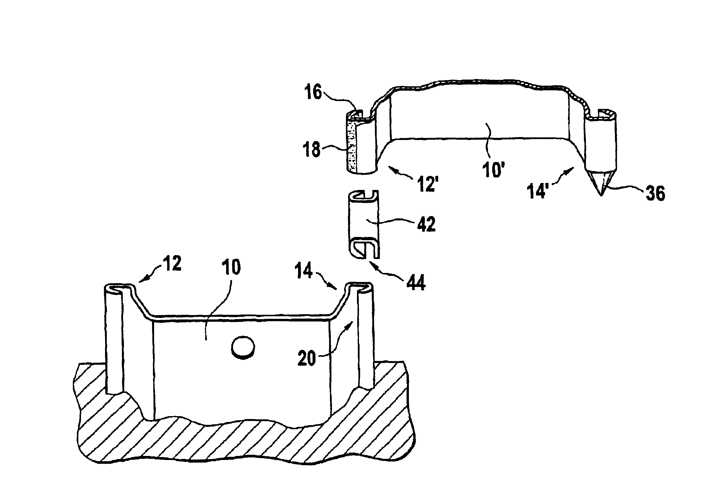
[0031]On FIG. 1, a first sheet pile 10 with its trailing and leading sheet pile interlocks 12, 14 can be seen in place in the ground. A second sheet pile 10′ with its trailing and leading sheet pile interlocks 12′, 14′ is ready to be interlocked with the first sheet pile 10. The trailing sheet pile interlock 12′ of the second sheet pile 10′ has an interlock head 16 coated with a fixing agent 18. This interlock head 16 engages in an interlock chamber 20 of the leading sheet pile interlock 14 of the first sheet pile 10. The interlock chamber 20 is clean, i.e. it is free from any ground material. The interlock head 16 of the trailing sheet pile interlock 12′ of the second sheet pile 10′ slides down the clean interlock chamber 20 of the leading sheet pile interlock 14 of the first sheet pile 10 as the second sheet pile 10′ is driven into the ground.

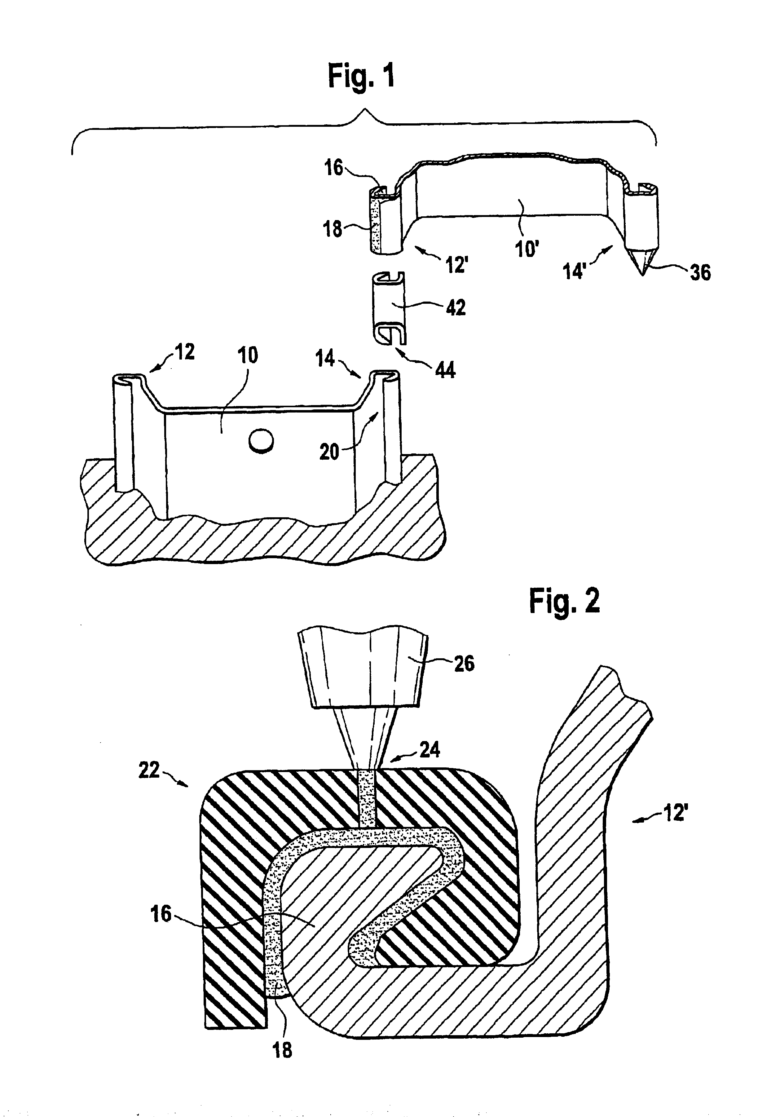
[0032]FIG. 2 shows a trailing sheet pile interlock 12′ whose interlock head 16 is being coated with a fixing agent 18. The fixing agent 18 i...


PUM

PropertyMeasurementUnit
flexibleaaaaaaaaaa
timeaaaaaaaaaa
massaaaaaaaaaa

Abstract

A method for building a sheet pile wall includes providing a first sheet pile having a leading sheet pile interlock with an interlock chamber, driving the first sheet pile into the ground while protecting the interlock chamber from ground material and providing a second sheet pile having a trailing sheet pile interlock with an interlock head. The method further includes coating a fixing agent as a surface layer on the interlock head of the trailing sheet pile interlock, engaging the coated interlock head of the trailing sheet pile interlock in the interlock chamber of the leading sheet pile interlock and driving the second sheet pile into the ground so that the trailing sheet pile interlock interlocks with the leading sheet pile interlock.

Description

FIELD OF THE INVENTION[0001]The present invention relates to a method for building sheet pile walls.BACKGROUND OF THE INVENTION[0002]The use of sheet piles for building retaining walls is well known. The sheet piles used in such walls have sheet pile interlocks along their longitudinal edges, which can be interlocked so as to maintain the longitudinal edges of adjacent sheet piles interconnected with each other. Current sheet pile interlocks of the double-hook interlock type (type 1 according to EN10248 norm), as e.g. LARSSEN type sheet pile interlocks, are hook shaped elements with an internal interlock chamber. A sheet pile wall is formed by driving a first sheet pile into the ground, introducing the bottom end of the trailing sheet pile interlock of a second sheet pile with the top end of the leading sheet pile interlock of the first sheet pile, driving the second sheet pile into the ground, and then repeating the process to insert third, fourth etc sheet piles into the wall.[000...

Claims


Application Information

Patent Timeline
Patent Type & Authority Patents(United States)
IPC IPC(8): E02D5/14E02D5/08
CPCE02D5/14
Inventor MOULIN, JEAN-MICHELRIX, ANDRÉ
Owner ARCELORMITTAL COMML RPS SRL
Why Eureka
Try Eureka