Air-conditioning apparatus

a technology for air-conditioning equipment and air-conditioning systems, which is applied in the direction of lighting and heating equipment, space heating and ventilation control systems, heating types, etc., and can solve problems such as affecting comfor

Active Publication Date: 2015-10-15
MITSUBISHI ELECTRIC CORP
View PDF0 Cites 20 Cited by
  • Summary
  • Abstract
  • Description
  • Claims
  • Application Information

AI Technical Summary

Benefits of technology

[0019]According to the present invention, an air-conditioning apparatus capable of performing high-efficiency defrosting, without stopping heat

Problems solved by technology

Therefore, there is a pro

Method used


Image

  • Air-conditioning apparatus
  • Air-conditioning apparatus
  • Air-conditioning apparatus

Examples


embodiment 1

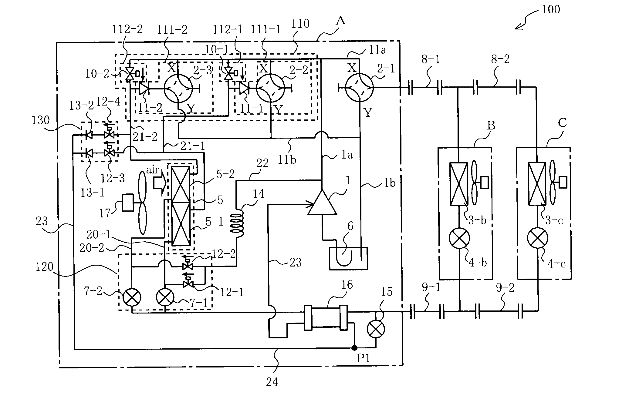
[0032]FIG. 1 is a refrigerant circuit diagram illustrating a refrigerant circuit configuration of an air-conditioning apparatus 100 according to Embodiment 1 of the present invention. In FIG. 1 and other figures mentioned below, parts referred to with the same signs correspond to the same parts or parts equivalent to the parts. The same applies throughout the description. Furthermore, forms of component parts illustrated in the description are merely exemplifications and are not limited to the described forms.

[0033]The air-conditioning apparatus 100 includes an outdoor unit A and indoor units B and C which are connected in parallel to each other. The outdoor unit A and the indoor units B and C are connected by first extension pipes 8-1 and 8-2 and second extension pipes 9-1 and 9-2. The air-conditioning apparatus 100 also includes a controller (not illustrated). The controller controls a cooling operation, and a heating operation (normal heating operation and heating and defrosting ...

embodiment 2

[0118]In Embodiment 2, all the valves in the first flow switching unit 110 and the second flow switching unit 120 in Embodiment 1 are four-way valves.

[0119]FIG. 10 is a refrigerant circuit diagram illustrating a refrigerant circuit configuration of an air-conditioning apparatus 200 according to Embodiment 2 of the present invention. Parts of Embodiment 2 which are different from Embodiment 1 will be mainly explained below.

[0120]In the air-conditioning apparatus 200, as the second connection switching devices 112-1 and 112-2 in Embodiment 1, the solenoid valves 10-1 and 10-2 are replaced with switching devices 112-1a and 112-2a described below. That is, in the switching devices 112-1a and 112-2a, check valves 11-3 and 11-4 are connected in series to third ports of four-way valves 2-1 and 2-4 whose first ports (high-pressure ports) X are connected to the high-pressure pipe 11a and second ports (low-pressure ports) Y are connected to the low-pressure pipe 11b so that a refrigerant flow...


PUM


Abstract

An air-conditioning apparatus divides an outdoor heat exchanger to form parallel heat exchangers and supplies part of refrigerant from a compressor to the parallel heat exchangers alternately to perform defrosting, performs medium-pressure defrosting in which part of the refrigerant from the compressor is decompressed and supplied to a parallel heat exchanger to be subjected to defrosting, and the refrigerant after being used for defrosting is injected into the compressor. A first flow switching unit performs switching of a connection mode of ends of the parallel heat exchangers on compressor side, where the pressure changes among high pressure, medium pressure, and low pressure according to operation contents, to one of three modes: a mode with the ends connected to the compressor discharge side, a mode with the ends connected to the compressor suction side, and a mode with the ends connected to neither the discharge nor suction side.

Description

TECHNICAL FIELD[0001]The present invention relates to an air-conditioning apparatus.BACKGROUND ART[0002]In recent years, in terms of global environmental protection, cases where heat-pump air-conditioning apparatuses which use air as a heat source are introduced even in cold regions, instead of known boiler-type heating devices which burn fossil fuels to perform heating, have increased. With heat-pump air-conditioning apparatuses, heating is able to be performed more efficiently by the amount of heat supplied from air, in addition to electric input to a compressor. In contrast, however, when the temperature of outside air is low, frost is deposited on an outdoor heat exchanger serving as an evaporator, it is therefore necessary to perform defrosting to melt frost deposited on the outdoor heat exchanger. As a method for performing defrosting, there is a method for reversing a refrigeration cycle. With this method, however, heating of a room is stopped during defrosting. Therefore, th...

Claims


Application Information

Patent Timeline
IPC IPC(8): F24F5/00F24F11/00
CPCF24F5/001F24F2011/0082F24F11/008F25B13/00F25B47/022F25B49/02F25B2313/0233F25B2313/02732F25B2313/0251F25B2400/13F25B2600/2515F24F11/84F24F11/83
Inventor TAKENAKA, NAOFUMIWAKAMOTO, SHINICHIYAMASHITA, KOJIHATOMURA, TAKESHI
Owner MITSUBISHI ELECTRIC CORP
Why Eureka
Try Eureka