Speech audio encoding device, speech audio decoding device, speech audio encoding method, and speech audio decoding method
a speech audio and decoding device technology, applied in the field of speech/audio coding apparatus, speech/audio decoding apparatus speech/audio coding method, can solve the problem of large error between the energy of the decoded spectrum and the subband energy, and achieve the effect of reducing the number of coded bits and preventing the deterioration of sound quality
- Summary
- Abstract
- Description
- Claims
- Application Information
AI Technical Summary
Benefits of technology
Problems solved by technology
Method used
Image
Examples
embodiment 1
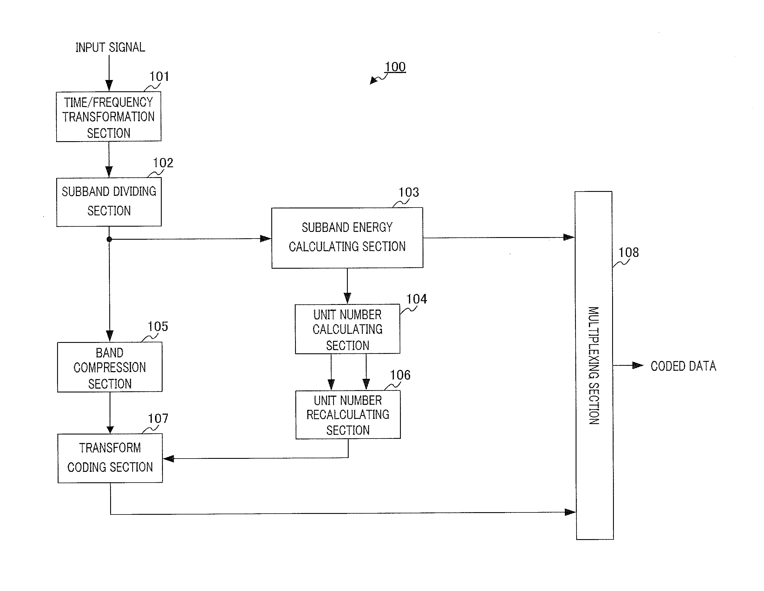
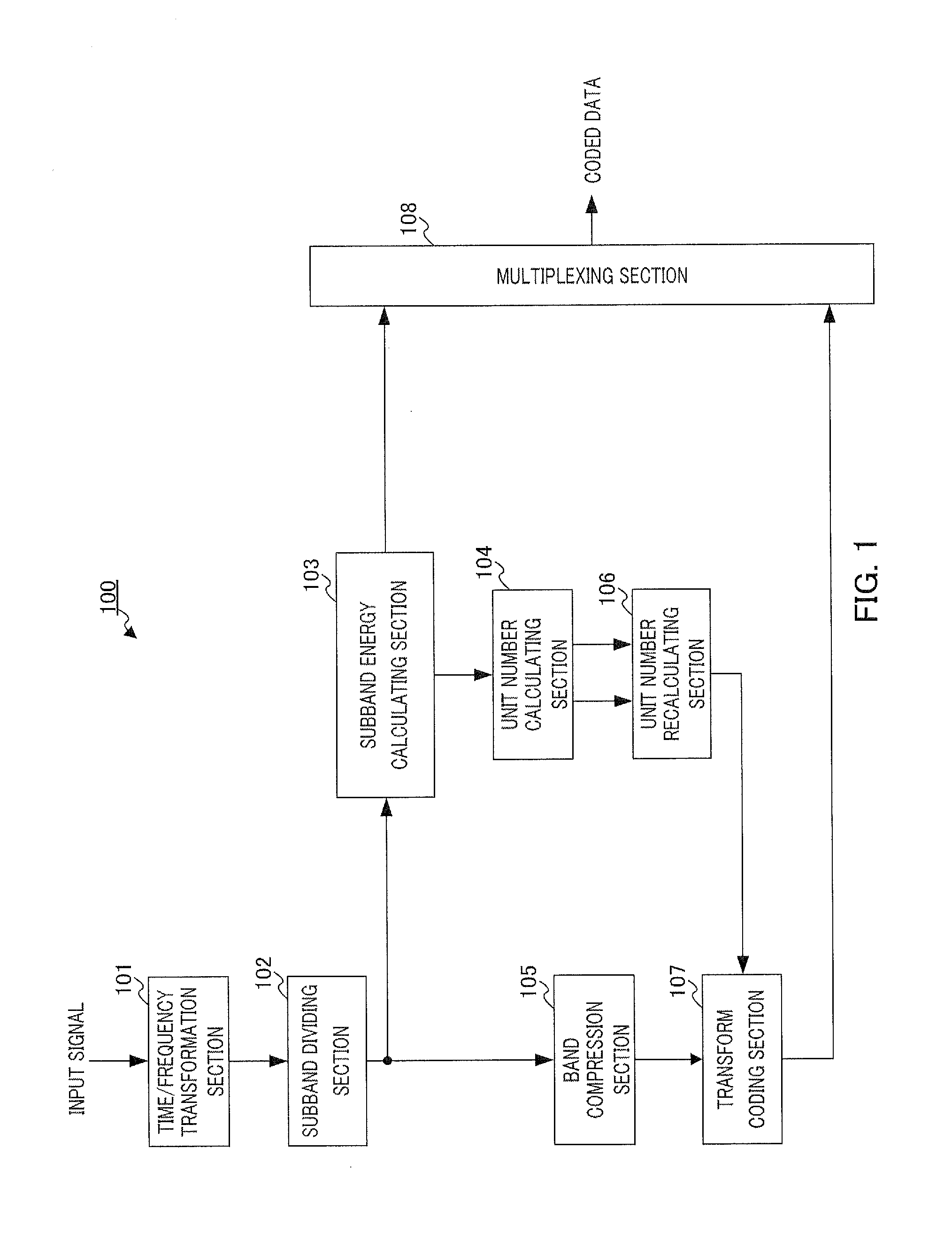
[0046]FIG. 1 is a block diagram illustrating a configuration of speech / audio coding apparatus 100 according to Embodiment 1 of the present invention. Hereinafter, the configuration of speech / audio coding apparatus 100 will be described using FIG. 1.
[0047]Time / frequency transformation section 101 acquires an input signal, transforms the acquired time-domain input signal to a frequency-domain signal and outputs the frequency-domain signal to subband dividing section 102 as an input signal spectrum. Note that in the embodiment, MDCT will be described as an example of time / frequency transformation, but orthogonal transformation such as FFT (Fast Fourier Transform) or DCT (Discrete Cosine Transform) may also be used.
[0048]Subband dividing section 102 divides the input signal spectrum outputted from time / frequency transformation section 101 into M subbands and outputs the subband spectrum to subband energy calculating section 103 and band compression section 105. With human perceptual cha...
embodiment 2
[0097]FIG. 8 is a block diagram illustrating a configuration of speech / audio coding apparatus 120 according to Embodiment 2 of the present invention. The configuration of speech / audio coding apparatus 120 will be described below using FIG. 8. FIG. 8 is different from FIG. 1 in that unit number recalculating section 106 is deleted, unit number calculating section 104 is changed to unit number calculating section 111 and subband energy attenuation section 121 is added.
[0098]Subband energy attenuation section 121 causes to attenuate, subband energy of the subband subject to band compression of the quantized subband energy outputted from subband energy calculating section 103 and outputs the attenuated subband energy to unit number calculating section 111.
[0099]The reason that the subband energy of the subband subject to band compression is caused to attenuate will be described here. If the subband energy is not caused to attenuate, as described in Embodiment 1, provisional allocation b...
embodiment 3
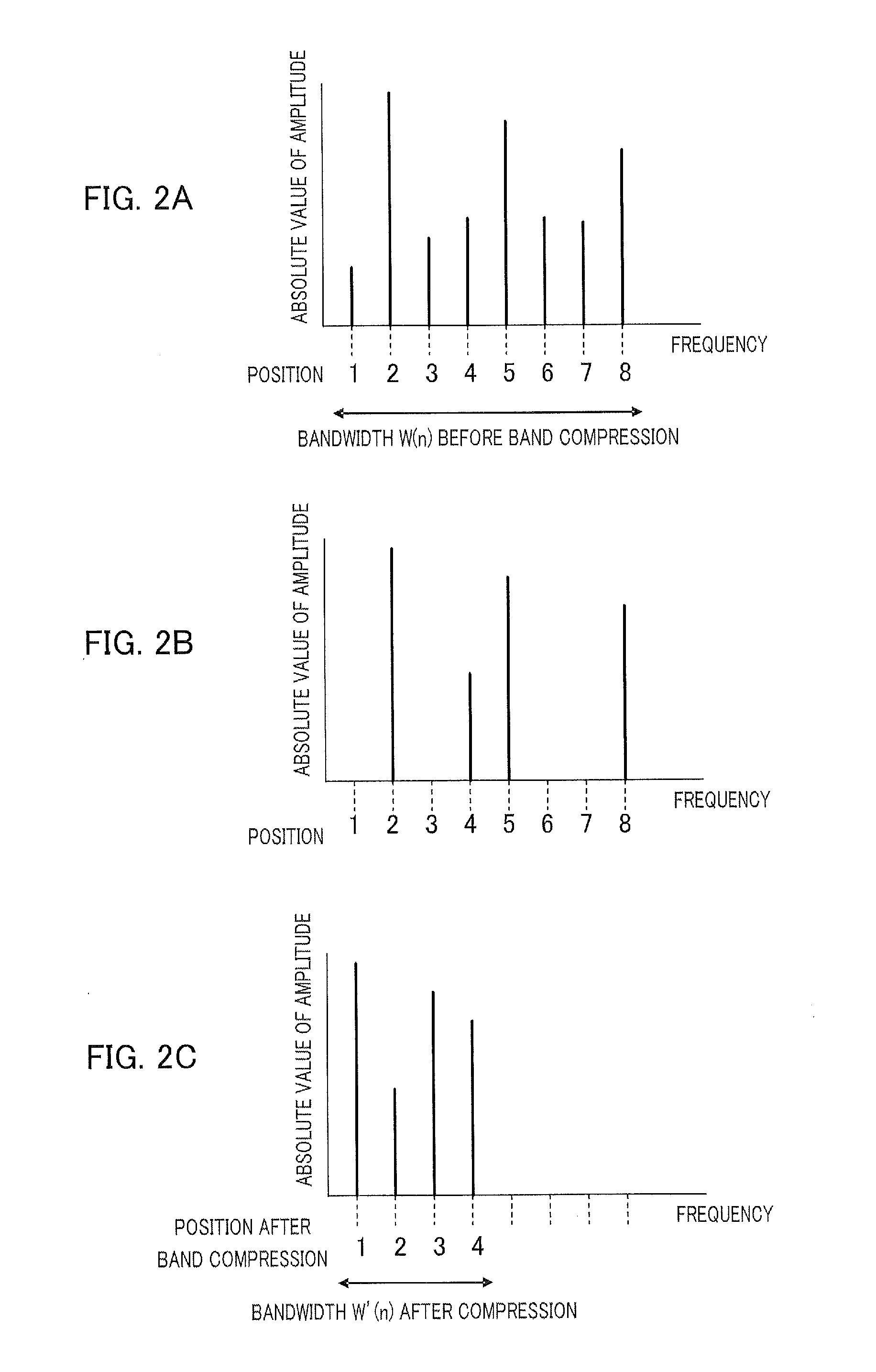
[0104]According to Embodiment 1, the spectrum position of the subband subject to band compression after extension may change from that of the subband before band compression. Thus, for at least a spectrum whose absolute value of amplitude that has a great influence on perception within a subband is a maximum spectrum (hereinafter referred to as “spectrum with maximum amplitude”), the spectrum position may be adapted so as not to change before and after band compression.
[0105]A case will be described in Embodiment 3 of the present invention where the position of a spectrum with maximum amplitude after decoding in the subband subject to band compression is corrected.
[0106]The configurations of a speech / audio coding apparatus and a speech / audio decoding apparatus according to Embodiment 3 of the present invention are similar to the configurations shown in Embodiment 1 in FIG. 1 and FIG. 4, and are different only in the functions of band compression section 105 and band extension sectio...
PUM
 Abstract
Description
Claims
Application Information
 - R&D
- Intellectual Property
- Life Sciences
- Materials
- Tech Scout
- Unparalleled Data Quality
- Higher Quality Content
- 60% Fewer Hallucinations
Browse by: Latest US Patents, China's latest patents, Technical Efficacy Thesaurus, Application Domain, Technology Topic, Popular Technical Reports.
© 2025 PatSnap. All rights reserved.Legal|Privacy policy|Modern Slavery Act Transparency Statement|Sitemap|About US| Contact US: help@patsnap.com


