Cutter

Inactive Publication Date: 2015-10-22
YU CHEN HSIU MAN
View PDF10 Cites 38 Cited by
  • Summary
  • Abstract
  • Description
  • Claims
  • Application Information

AI Technical Summary

Benefits of technology

[0011]The cutting unit wrapped by the main body has the cutter edge to carry out cutting of packaging members, avoiding any damages to the articles in a packing box. Packaging members that are seamless and have their edges closely attached to a packing box can be cut off by the pointed end portion of the cutter. This is able to cut

Problems solved by technology

For unsealing a packing box, a craft knife is often employed to cut off and remove every sort of packaging members fastened on the box and this method is unquestionable in point of technical level, but using the knife point to be a chief force-applying point of cutting will often cause in

Method used


Image

  • Cutter
  • Cutter
  • Cutter

Examples


Example

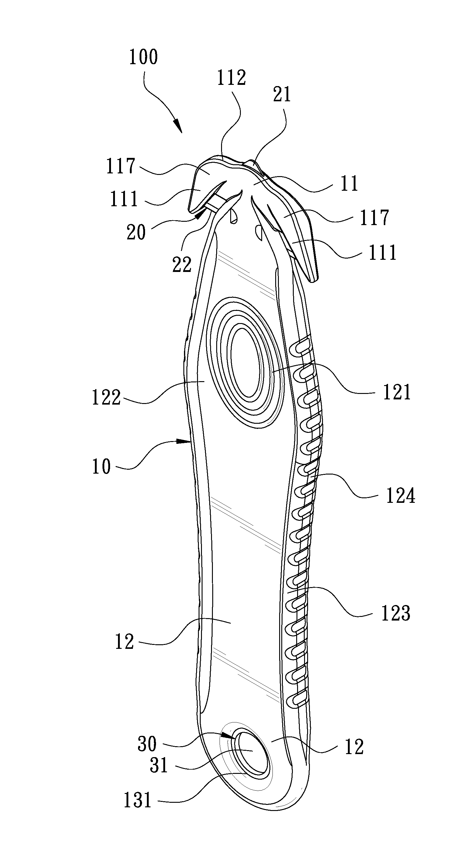
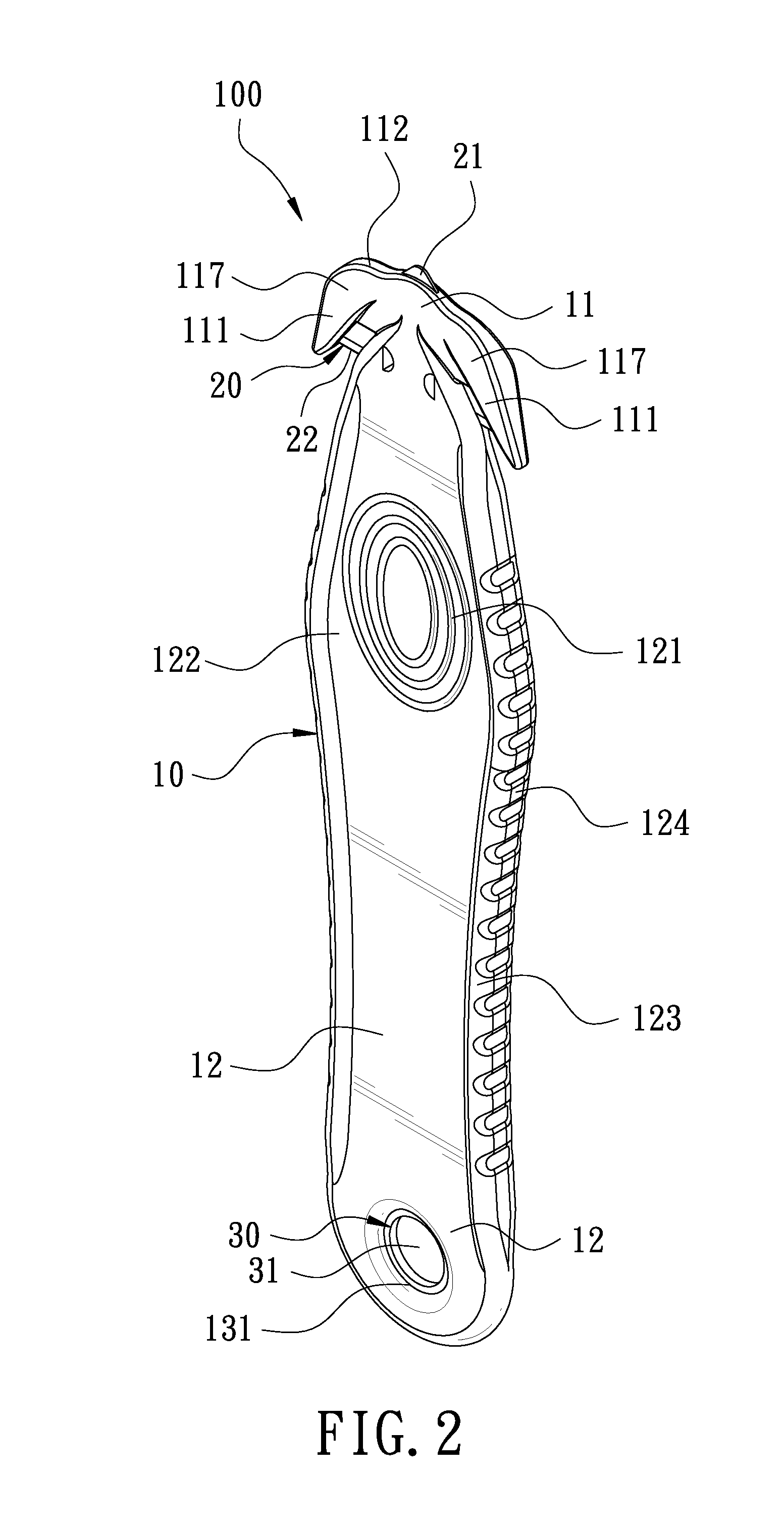
[0025]FIG. 2 is a perspective view according to a first embodiment of the present invention. The present invention discloses a cutter 100. The cutter 100 comprises a main body 10, a cutting unit 20, and a magnetic member 30.

[0026]The main body 10 is an elongate plate body made of plastic. Two lengthwise ends of the main body 10 are defined as a first end portion 11 and a second send portion12, respectively. Referring to FIG. 4 and FIG. 5, the first end portion 11 of the main body 10 is provided with an accommodation space 114. A central portion of a top edge of the first end portion 11 of the main body 10 is provided with a first opening 115. The first opening 115 is in communication with the accommodation space 114. The first end portion 11 of the main body 10 is gradually reduced toward the top edge thereof. The top edge of the first end portion 11 is provided with a holding portion 112 close to the circumferential side of the first opening 115. The holding portion 112 is a holdin...

Example

[0037]FIG. 12 is a perspective view according to a second embodiment of the present invention. The second embodiment is substantially similar to the first embodiment with the exceptions described hereinafter. Front and rear surfaces of the first end portion 11, relative to the working surfaces of the pointed end portion 21 of the cutting unit 20, are provided with protection lids 113. The protection lids 113 each are slightly less than the working surfaces of the pointed end portion 21 of the cutting unit 20, such that at least one side edge of the pointed end portion 21 of the cutting unit 20 is exposed to be a V-shaped working surface.

[0038]Although particular embodiments of the present invention have been described in detail for purposes of illustration, various modifications and enhancements may be made without departing from the spirit and scope of the present invention. Accordingly, the present invention is not to be limited except as by the appended claims.


PUM


Abstract

A cutter includes a main body. The top edge of the main body is provided with a holding portion, and its two sides extend outward to form a pair of lugs. A pair of gaps is formed between the main body and the pair of lugs. The cutter further includes a cutting unit wrapped by the main body. The cutting unit has one side formed with a pointed end portion and another side formed with a cutter edge. The pointed end portion protrudes out of the holding portion, and the cutter edge is exposed out of the gaps. The multi-function cutter is able to cut and remove various packaging members easily and efficiently.

Description

[0001]The current application is a continuation-in-part of U.S. application Ser. No. 13 / 724845 filed on Dec. 21, 2012.BACKGROUND OF THE INVENTION[0002]1. Field of the Invention[0003]The present invention relates to a cutter, and more particularly to a multi-function cutter able to cut off and remove various kinds of packaging members.[0004]2. Description of the Prior Art[0005]In general, for facilitating articles to be carried and transported, the articles are usually boxed or bagged for protection and, after the articles are packed in a box, and even the box itself is tied up by plastic packaging straps for insuring the articles to be kept intact in the box. For unsealing a packing box, a craft knife is often employed to cut off and remove every sort of packaging members fastened on the box and this method is unquestionable in point of technical level, but using the knife point to be a chief force-applying point of cutting will often cause injuries to the articles in the packing bo...

Claims


Application Information

Patent Timeline
IPC IPC(8): B26B27/00
CPCB26B27/005B26B3/00
Inventor YU CHEN, HSIU-MAN
Owner YU CHEN HSIU MAN
Why Eureka
Try Eureka