Inkjet printer

a printer and inkjet technology, applied in the field of inkjet printers, can solve the problems of ink in the ink chamber to be ejected from the nozzle, decrease in ejection speed, misalignment of ink onto the sheet, etc., and achieve the effect of further reducing the degradation of print quality

Active Publication Date: 2015-10-22
RISO KAGAKU CORP
View PDF2 Cites 12 Cited by
  • Summary
  • Abstract
  • Description
  • Claims
  • Application Information

AI Technical Summary

Benefits of technology

[0019]In the above-described configuration, since the corrected waveform is adjusted according to the temperature of ink, misaligned ink landing and print quality degradation can be further reduced.

Problems solved by technology

The deformations of the partition walls cause changes in the volumes and the pressures in the ink chambers, and cause ink in the ink chambers to be ejected from the nozzles.
A decrease in the ejection speed of ink causes the misaligned landing of ink onto a sheet.
Moreover, a decrease in the ejection amount of ink makes flying ink prone to be drifted by an air stream.
Accordingly, a decrease in the ejection amount of ink also contributes to misaligned ink landing.
Misaligned ink landing causes print quality degradation.

Method used


Image

  • Inkjet printer
  • Inkjet printer
  • Inkjet printer

Examples


Embodiment Construction

[0035]In the following detailed description, for purposes of explanation, numerous specific details are set forth in order to provide a thorough understanding of the disclosed embodiments. It will be apparent, however, that one or more embodiments may be practiced without these specific details. In other instances, well-known structures and devices are schematically shown in order to simplify the drawing.

[0036]Description will be hereinbelow provided for an embodiment of the present invention by referring to the drawings. It should be noted that the same or similar parts and components throughout the drawings will be denoted by the same or similar reference signs, and that descriptions for such parts and components will be omitted or simplified. In addition, it should be noted that the drawings are schematic and therefore different from the actual ones.

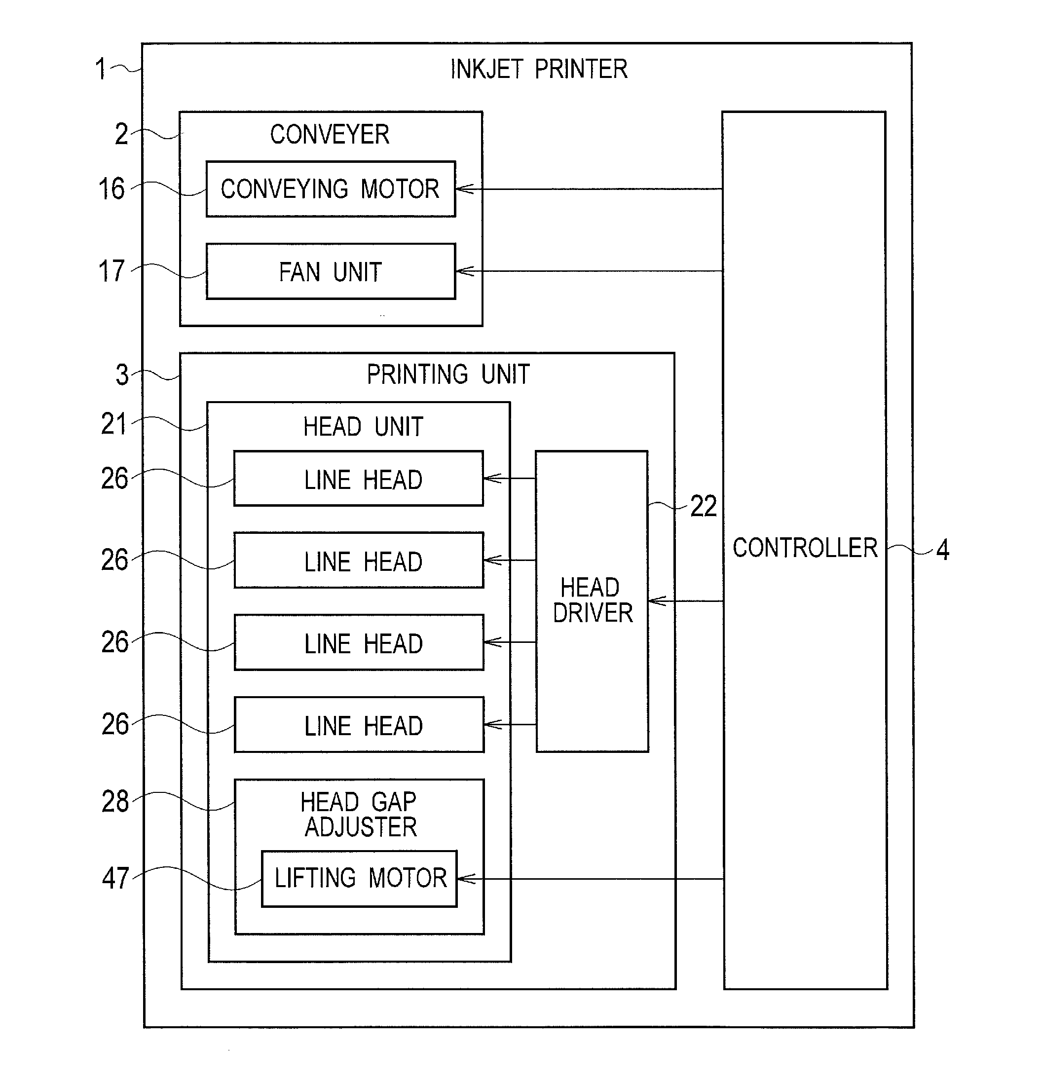
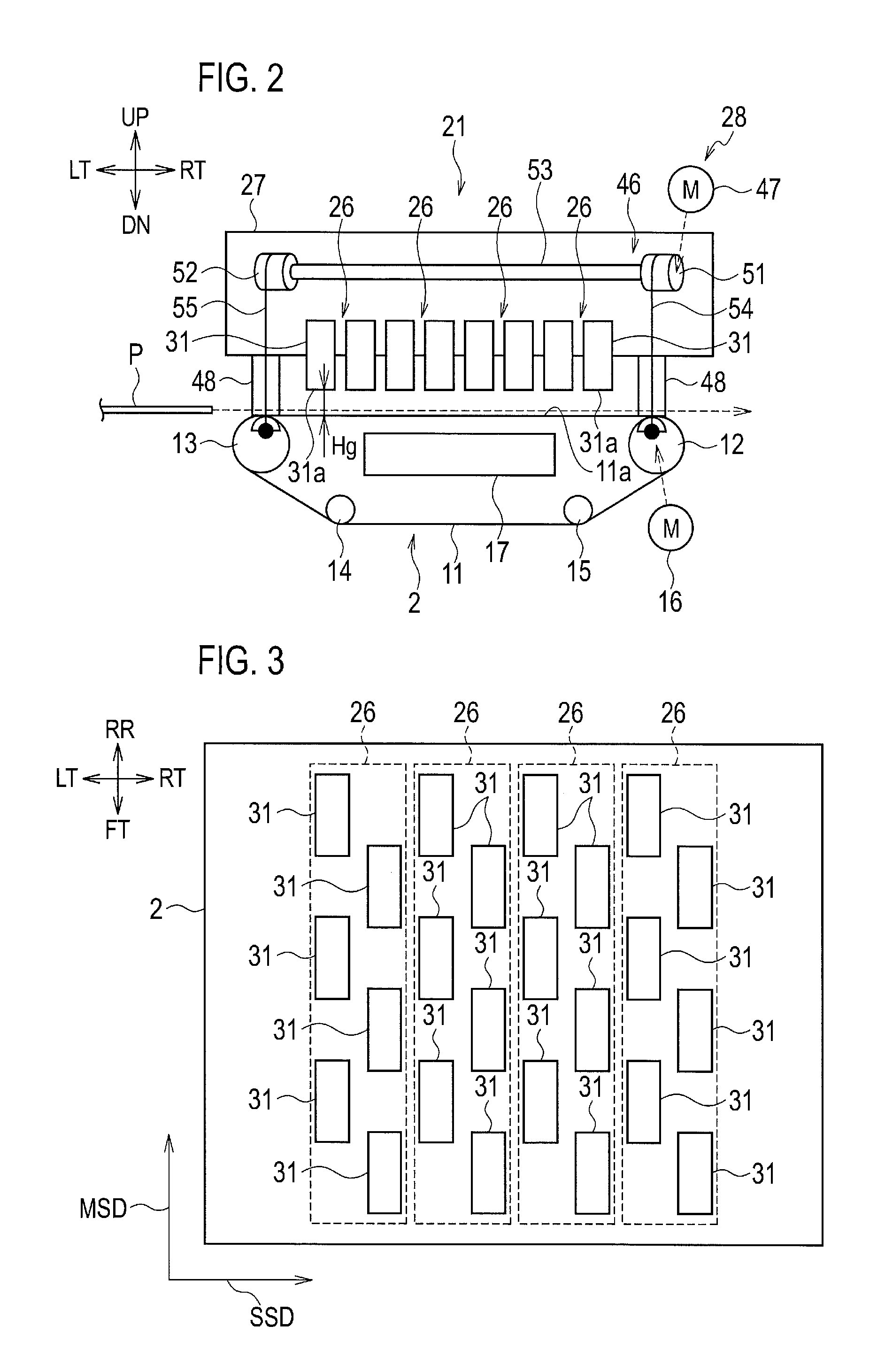
[0037]FIG. 1 is a block diagram showing the configuration of an inkjet printer according to an embodiment of the present invention. ...


PUM


Abstract

Upon driving a driver to perform an ejection drive of each of ink chambers subjected to the ejection drive, a controller drives the driver to supply a drive signal having a corrected waveform which increases an ejection amount and an ejection speed of ink compared with those of a normal waveform, when a correction condition is satisfied. The correction condition includes that at least one of the ink chambers arranged next to the ink chamber subjected to the ejection drive is not subjected to the ejection drive in an immediately preceding time slot, and that both the ink chambers arranged next to the ink chamber subjected to the ejection drive in a same group are subjected to the ejection drive.

Description

CROSS REFERENCE TO RELATED APPLICATION[0001]This application is based upon and claims the benefit of priority from the prior Japanese Patent Application No. 2014-084518, filed on Apr. 16, 2014, the entire contents of which are incorporated herein by reference.BACKGROUND[0002]1. Technical Field[0003]The present invention relates to an inkjet printer which performs printing by ejecting ink from an inkjet head.[0004]2. Related Art[0005]An inkjet printer including a shear-mode inkjet head is described in Japanese Unexamined Patent Application Publication No. H7-17039.[0006]The shear-mode inkjet head includes a plurality of ink chambers arranged next to one another in a row. Each ink chamber has a nozzle communicating therewith. The ink chambers are isolated from each other by partition walls, each partition wall including two piezoelectric members polarized in different directions. Electrodes are provided on surfaces of the partition walls. Drive signals applied to the electrodes cause ...

Claims


Application Information

Patent Timeline
Patent Type & Authority Applications(United States)
IPC IPC(8): B41J2/045
CPCB41J2/04581B41J2/04588B41J2/04505B41J2/04595B41J2/04596B41J2/14209
Inventor SHIMODA, ASAYO
Owner RISO KAGAKU CORP
Why Eureka
Try Eureka