Optical disc and recording/producing method therefor

a technology of optical discs and recording/producing methods, applied in the field of optical disc formatting, can solve the problems of increasing data reproduction errors, clock signals may not be extracted, and it is difficult to design a multi-layer recordable optical disc, so as to reduce the crosstalk between the signal light beam from the header area and the signal light beam from the recording-data area

Inactive Publication Date: 2008-08-19
NEC CORP
View PDF5 Cites 5 Cited by
  • Summary
  • Abstract
  • Description
  • Claims
  • Application Information

AI Technical Summary

Benefits of technology

[0035]The present invention has been devised in view of the foregoing. An object of the invention is to provide an optical disc having a simple configuration and a large storage capacity by allowing a disc format that can be applied to optical discs of land / groove recording type, each having a plurality of recording layers.
[0037]In an optical disc according to the present invention, the header areas of the recording layer located near the light-incident side are not aligned in the radial direction of the disc. Therefore, the quality degradation of signals reproduced from the disc can be decreased, in spite of the inter-layer crosstalk that develops when a beam is focused on the recording layer that lies remote from the optical head.
[0039]In the recording / reproducing method according to the present invention, the user data is not recorded in portions of the land areas adjacent to the header areas in the radial direction or in the data-recording areas of the groove areas. Hence, the crosstalk between the signal light beam from a header area and the signal light beam from a recording-data area can be decreased.

Problems solved by technology

However, it is difficult to design a multi-layer recordable optical disc even if the disc has only two recording layers.
As to the reproducing performance, if the transmittance of each recorded mark extremely differs from that of each unrecorded part, the recorded mark will be reproduced at a small SNR, thereby increasing errors in data reproduction.
Consequently, the clock signal may not be extracted or the bit error rate may be greatly increased.

Method used


Image

  • Optical disc and recording/producing method therefor
  • Optical disc and recording/producing method therefor
  • Optical disc and recording/producing method therefor

Examples


first embodiment

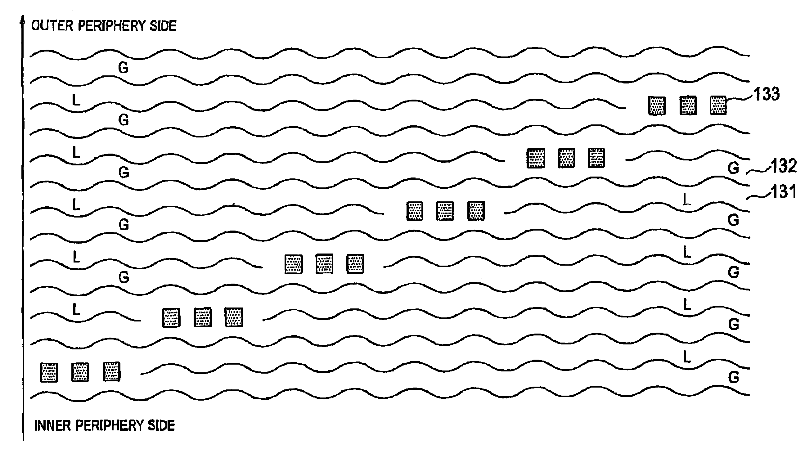
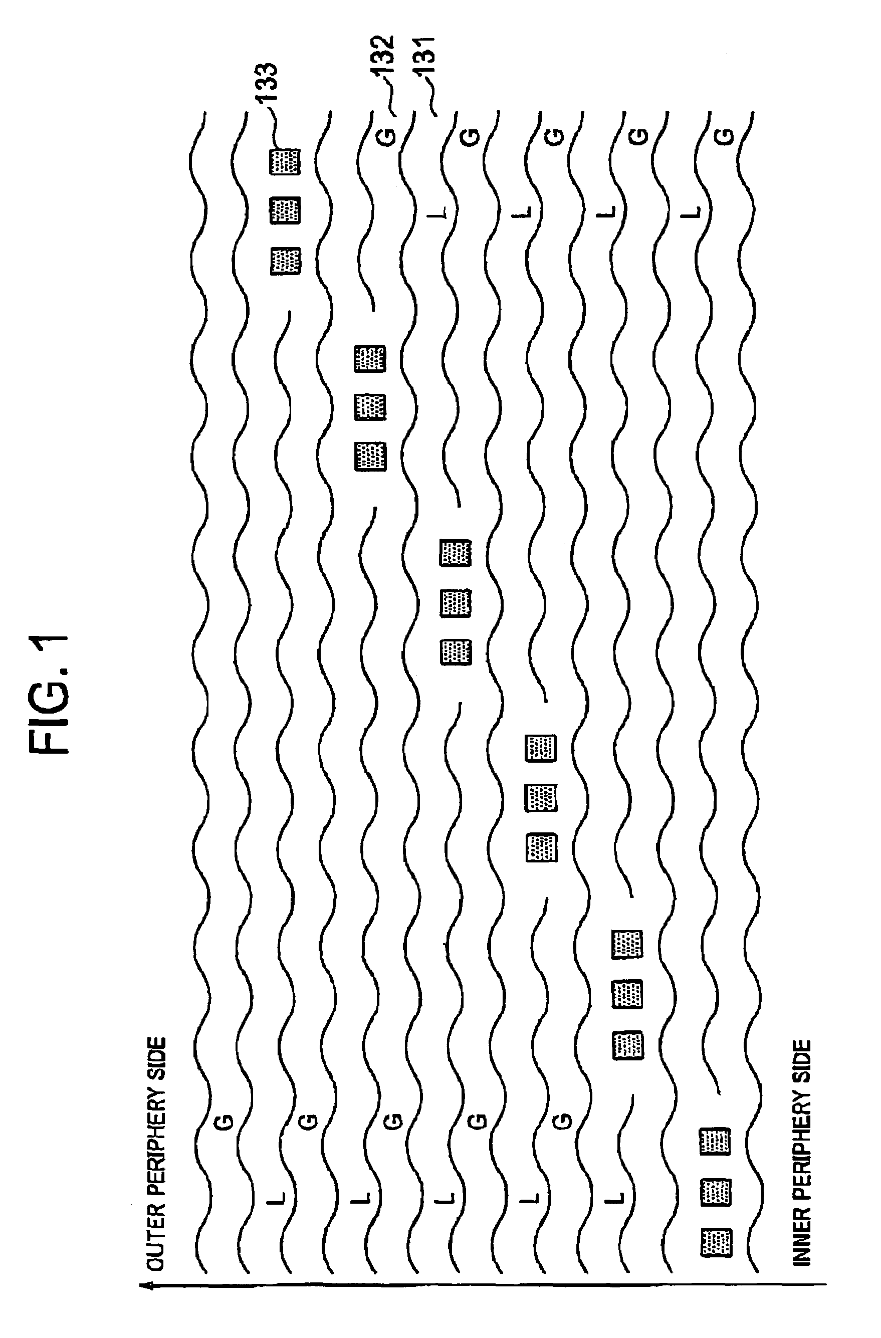
[0064]FIG. 1 shows the surface configuration of the recording layer 10, which is one of the two recording layers of an optical disc according to this embodiment, and lies near the light source of an optical head. The wobbles shown in FIG. 1. i.e., meandering lines, are schematic ones. The number of the wobbles is not equal to the number of waves, which will be described later.

[0065]As FIG. 1 depicts, the header areas are arranged between the data-recording areas and equally spaced from one another in the scanning direction of the light beam in the data-recording areas, that is, in the circumferential direction of the optical disc. The data-recording areas including land areas 131 (i.e., areas L), which are convex portions of the optical disc, and adjacent groove areas 132 (i.e., areas G), which are concave portions. Further, prepit areas are located each on an every other boundary between a land area L and a groove area G. Each prepit area includes prepits 133 that represent physica...

second embodiment

[0069]In an optical disc according to this embodiment, the change of the Hal generated from the light reflected by the recording layer near the light-incident side is at most 10% of the amplitude of the signal generated from the light reflected by We recorded mark / space which includes trains of prepits and which is provided on the other recording layer on which a light beam is focused.

[0070]For example, when a light beam is focused on the recording layer 20 to record or reproduce data, the beam passing the recording layer 10 has a diameter of about 44 μm, as described above. The light beam reflected from the recording layer 10 including the header areas irradiated by the beam spot is superposed on the light beam reflected from the recording layer 20. The light-receiving element incorporated in the optical head receives both light beams, superposed one on the other.

[0071]As described before in the problems with the prior art, the data reproduced cannot be correctly identified if the ...

third embodiment

[0076]In an optical disc according to this embodiment, the groove areas wobble at a frequency that is an integral multiple of the channel-clock frequency and are aligned, in each zone, in the radial direction of the disc.

[0077]As FIG. 1 shows, the groove areas may be formed in each zone by the intra-zone CAM system and may therefore wobble, forming wobbles, at a frequency that is an integral multiple of the channel-clock frequency. In this case, the wobbles will be aligned in the radial direction of the disc. In a two-layer optical disc, for example, the inter-layer crosstalk developing when data is recorded / reproduced on the recording layer 20 causes only a negligibly small interference even if the groove areas wobble on the recording layer 10 at a prescribed frequency.

[0078]The wobbles formed are aligned in the radial direction of the disc. As a result, wobble signals that have no distortion like the signals reproduced from the groove areas are detected in the land areas. A desira...


PUM

PropertyMeasurementUnit
distanceaaaaaaaaaa
refractive indexaaaaaaaaaa

Abstract

An optical disc including one or more than one recording layers has land areas (131) and groove areas (132) as recording tracks, wherein a data recording area of at least one of the recording layers is divided into a plurality of zones in a radial direction. In each of the divided zones, one or more than one prepits (133) with predetermined data are disposed in a track so that each header area is disposed at ever other boundary among the boundaries between the land areas and the groove areas. Each header area is shifted in the circumferential direction from other header areas apart from the each header area by two boundaries without overlapping in the radial direction.

Description

CROSS-REFERENCE TO RELATED APPLICATION[0001]The present application is a continuation of International Application No. PCT / JP2003 / 006643, which was filed on May 28, 2003, which is herein incorporated by reference[0002]1. Technical Field[0003]The present invention relates to formatting of an optical disc. More particularly, the present invention relates to an optical disc capable of employing a disc formatting scheme suitable for multi-layer discs and to a recording / reproducing method therefor.[0004]2. Background Art[0005]To reproduce signals from any optical disc used at present, a technique is used wherein a laser beam reflected from the optical disk while being modulated thereby is used to detect reproduced signals. From a read-only optical disc, for example, signals are reproduced by detecting the changes in intensity of the laser beam reflected from the pits configuring concavity and convexity on the disc. From a write-once optical disc, signals are reproduced by detecting the c...

Claims


Application Information

Patent Timeline
Patent Type & Authority Patents(United States)
IPC IPC(8): G11B7/24G11B7/004G11B7/007G11B7/24038G11B20/10G11B20/12
CPCG11B7/00718G11B7/24038G11B7/00745
Inventor IWANAGA, TOSHIAKI
Owner NEC CORP
Why Eureka
Try Eureka