Multi-Stage Vacuum Ejector With Molded Nozzle Having Integral Valve Elements

a vacuum ejector and multi-stage technology, applied in the field of vacuum ejectors, to achieve the effect of more cost-efficien

Active Publication Date: 2015-10-22
PIAB
View PDF18 Cites 11 Cited by
  • Summary
  • Abstract
  • Description
  • Claims
  • Application Information

AI Technical Summary

Benefits of technology

[0024]Relative to the prior art discussed above, the invention renders the manufacturing of an at least equally efficient multi-stage ejector more cost-efficient.

Problems solved by technology

Although such multi-stage ejector arrangements are beneficial in providing both a high-volume flow rate and a high level of negative pressure, there is necessarily still some degree of compromise in the design of each successive stage in the ejector, in order to obtain an overall desired performance characteristic for the multi-stage ejector as a whole.

Method used


Image

  • Multi-Stage Vacuum Ejector With Molded Nozzle Having Integral Valve Elements
  • Multi-Stage Vacuum Ejector With Molded Nozzle Having Integral Valve Elements
  • Multi-Stage Vacuum Ejector With Molded Nozzle Having Integral Valve Elements

Examples


first embodiment

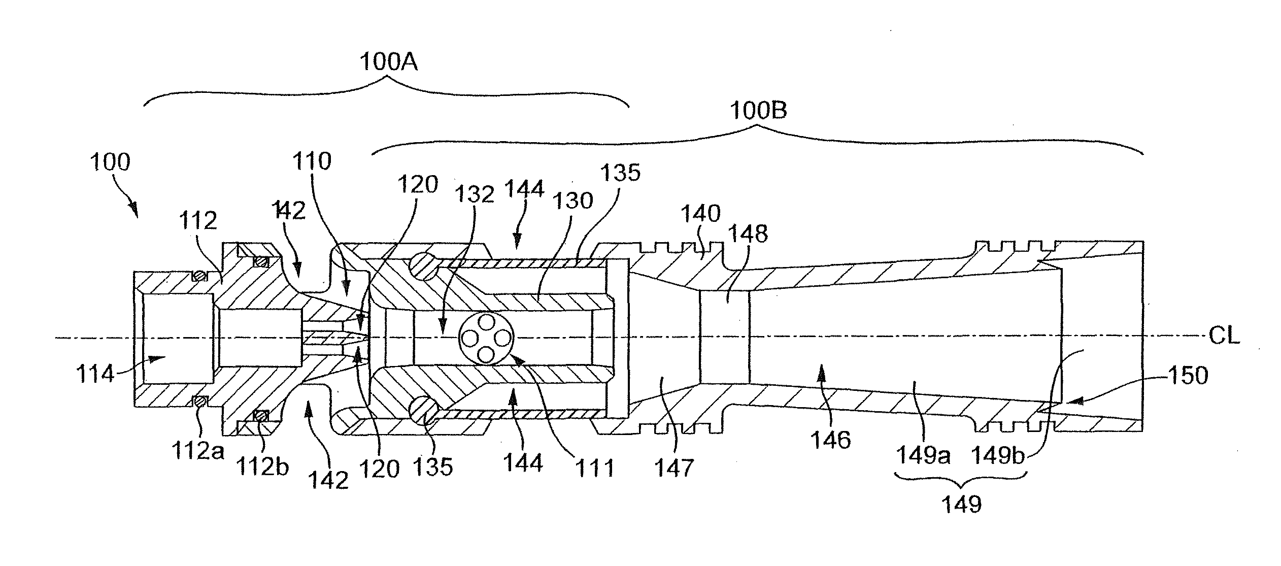
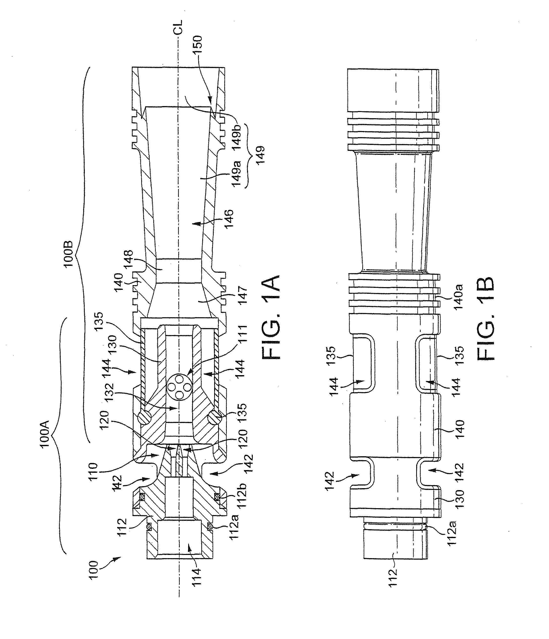
[0047]FIGS. 1A and 1B show an ejector according to the present invention. The embodiment of FIGS. 1A and 1B is configured as an ejector cartridge 100. Such a cartridge is intended to be installed within an ejector housing module, or within a bore or chamber formed in an associated piece of equipment, which defines the volume to be evacuated by the ejector cartridge.

[0048]Although the most preferred embodiment of the ejector, as shown in the drawings, is designed to work with air as the drive fluid, and as the fluid to be evacuated, the ejector will be applicable to any gas as the drive fluid, and any gas as the fluid to be evacuated. The drive fluid will have a primary direction of movement, or flow, through the ejector. This direction is parallel to the longitudinal axis of the ejector, shown horizontally in the drawings, and starting from the inlet 114. In the following, this direction will be referred to as the direction of airflow.

[0049]Ejector cartridge 100 is a multi-stage eje...

second embodiment

[0079]Turning to FIGS. 5A, 5B, 6, 7A to 7C and 8, there is shown an ejector according to the present invention. The embodiment of FIGS. 5A, 5B, 6, 7A to 7C and 8 is also configured as an ejector cartridge 200.

[0080]The ejector 200 is similar in construction and operation to the ejector 100, and the description above of the features, components, operation and use of the ejector 100 applies equally to the ejector 200, except where further features or variations are particularly explained. Again, ejector cartridge 200 includes a first, drive stage 200A and a second stage 200B.

[0081]FIG. 5B is an axial end view, facing towards the exit end of the ejector 200, which clearly shows the outlets of the drive nozzles 220 arranged in a grouping so as to face into and along the axial passage defined by the second stage nozzle 232 and the exit nozzle 246. FIG. 5A shows the section A-A of FIG. 5B, which contains the centre axis CL, about which the ejector cartridge 200 substantially forms a body ...


PUM

PropertyMeasurementUnit
feed pressuresaaaaaaaaaa
angleaaaaaaaaaa

Abstract

So as to render the manufacturing of an at least equally efficient multi-stage ejector more cost-efficient, the invention provides a multi-stage ejector for generating a vacuum from a source of compressed air by passing said compressed air through a series of nozzles, accelerating said compressed air, and entraining air so as to form a jet flow in one or more stages and generate a vacuum across each stage, the multi-stage ejector comprising a drive stage; a second stage; and a converging-diverging nozzle provided in said series of nozzles between said drive stage and said second stage for receiving jet flow from said drive stage and accelerating said jet flow to form a second stage air jet and directing said second stage air jet into an inlet of an outlet nozzle of the second stage, wherein said converging-diverging nozzle is formed in a moulded nozzle piece mounted in said multi-stage ejector.

Description

TECHNICAL FIELD[0001]The present invention relates to vacuum ejectors driven by compressed air.BACKGROUND ART[0002]Vacuum pumps are known which use a source of compressed air (or other high-pressure fluid) in order to generate a negative pressure or vacuum in a surrounding space. Compressed-air driven ejectors operate by accelerating the high pressure air through a drive nozzle and ejecting it as an air jet at high speed across a gap between the drive nozzle and an outlet flow passage or nozzle. Fluid medium in the surrounding space between the drive nozzle and outlet nozzle is entrained into the high-speed flow of compressed air, and the jet flow of entrained medium and air originating from the compressed-air source is ejected through the outlet nozzle. As the fluid in the space between the drive and outlet nozzles is ejected in this way, a negative pressure or vacuum is created in the volume surrounding the air jet which this fluid or medium previously occupied.[0003]For any given...

Claims


Application Information

Patent Timeline
Patent Type & Authority Applications(United States)
IPC IPC(8): F04F5/22F04F5/46
CPCF04F5/467F04F5/22F04F5/54
Inventor TELL, PETER
Owner PIAB
Why Eureka
Try Eureka