Method for optical detection of an adjoining of a material component to a sensor material with the aid of biological, chemical or physical interaction and device for carrying out said method (variants)

a technology of biological, chemical or physical interaction and optical detection, applied in the direction of material testing goods, biochemistry equipment and processes, biochemistry apparatus and processes, etc., can solve the problems of insufficient reliability, low sensitivity, low precision, etc., to reduce labor input and cost, simplify the method, and reduce the number of necessary operations

Inactive Publication Date: 2003-10-09
PETR IVANOVICH NIKITIN
View PDF9 Cites 10 Cited by
  • Summary
  • Abstract
  • Description
  • Claims
  • Application Information

AI Technical Summary

Benefits of technology

[0085] As the thickness of the sensor layer exceeds wavelengths of the recorded spectrum by one or more orders of magnitude, frequencies of the recorded spectrum significantly exceed the frequency period of the interference pattern .DELTA..nu., and maximums or minimums corresponding to larger values of .DELTA..nu. are observed in the recorded spectrum. Hence, it is spectral shift of the interference maximums and minimums that is first of all observed at a change of thickness of the sensor layer, and this shift is a much more pronounced effect that a change of distance between maximums or minimums in the recorded spectrum. When thickness of the sensor layer is sufficiently large as compared with operating wavelengths, the spectrum of operating wavelengths is wide enough, and at most common in practice low reflection coefficients of the boundary surfaces of the sensor layer the interference pattern in the recorded spectrum has many periods and can be considered with good accuracy as a sinusoid or, more precisely, a sinusoid modulated by spectrum of the affecting light. In this case, tracking of phase of the said sinusoid can be a convenient method to obtain an information signal. To take into account the modulated character of the sinusoid, it is convenient to apply the fast Fourier transformation to the recorded spectrum containing the interference pattern and to track the phase of the first harmonic.
[0160] The preferable realization of the multi-channel method consists in registration of the said distribution for each said area by using sequentially in time different values of base of the scanned Fabry-Perot interferometer and measuring at each said value the intensity of the said reflected or transmitted light, summed up over the said spectral interval, for each said area (claim 36). This allows recording of the said distribution point-by-point in parallel for all said areas of the sensor layer, each point corresponding a single value of the interferometer base. In this case, it is sufficiently to use only one scanned Fabry-Perot interferometer to study binding of components in a large number of areas of the sensor layer. This simplifies the method, makes it more cost-efficient and provides the required technical result. The simplest multi-channel modification is realized when all the areas are simultaneously irradiated by light (claim 37). For example, the interferometer is located before the sensor layer on the pathway of the parallel light beam; the beam is widened after the interferometer, e.g. by a telescopic scheme; the resulting wide parallel beam is used for irradiating of all said areas. It is the simplest realization of the proposed variant of the method, which provides maximal accuracy and reliability of measurement results, and, consequently, the required technical result.

Problems solved by technology

Drawbacks of the analogue and the apparatus for its embodiment [U.S. Pat. No. 4,558,012, Int. Cl. G01N 33 / 54, U.S. Cl. 436 / 501, 1985] are its low sensitivity, not sufficient reliability and low precision of the results.
Besides, these method and apparatus do not permit real-time registration of binding of chemical substances and investigation of kinetics of the process.
Moreover, they are also more complex and less reliable because of using of the said metallic film.
The mentioned limitations are due to the principle of how the absolute thickness of the sensor layer is determined in the method-analogue.
Employment of thicker sensor layers would result in interference pattern with many periods in the recorded spectrum.
Unambiguous determination of the absolute thickness of the sensor layer from such interference pattern would be difficult or impossible.
The mentioned principle and related limitations on thickness of the sensor layer give rise to a number of drawbacks of the method-analogue.
Due to this fact, any intensity variations in the recorded spectrum lead to significant errors in the measurement results.
Since in the method of multi-channel registration different spectral regions are recorded sequentially in time, any drifts and instabilities in intensity of the analyzed light in whole or in any region of its spectrum result in lower accuracy of measurements.
Such instabilities cause not only drifts of spectral distribution of the light intensity in each channel, but also drifts of intensity distribution of the analyzed light over the channels.
In these cases, uncontrollable drifts of both spectrum of the analyzed light and intensity distribution over the registration channels take place.
All this leads to low sensitivity, insufficient resolution, low reliability and precision of results obtained by the method-analogue [DE 42 00 088 C2, Int. Cl. G01N 21 / 45, 1997] and especially its multi-channel variant [U.S. Pat. No. 5,999,262, Int. Cl. G01B 9 / 02, U.S. Cl. 356 / 357, 1999].
Complexity, high labor input and cost can be mentioned among drawbacks of the method and, even more, its multi-channel variant.
The mentioned peculiarities and restrictions of the apparatus-analogue give rise to a number of drawbacks discussed earlier while analyzing the corresponding method, namely, significant errors in measurement results due to uncontrollable intensity variations over the recorded spectrum or its intervals, low sensitivity and resolution, low precision and insufficient reliability of results of measurements.

Method used


Image

  • Method for optical detection of an adjoining of a material component to a sensor material with the aid of biological, chemical or physical interaction and device for carrying out said method (variants)
  • Method for optical detection of an adjoining of a material component to a sensor material with the aid of biological, chemical or physical interaction and device for carrying out said method (variants)

Examples


Embodiment Construction

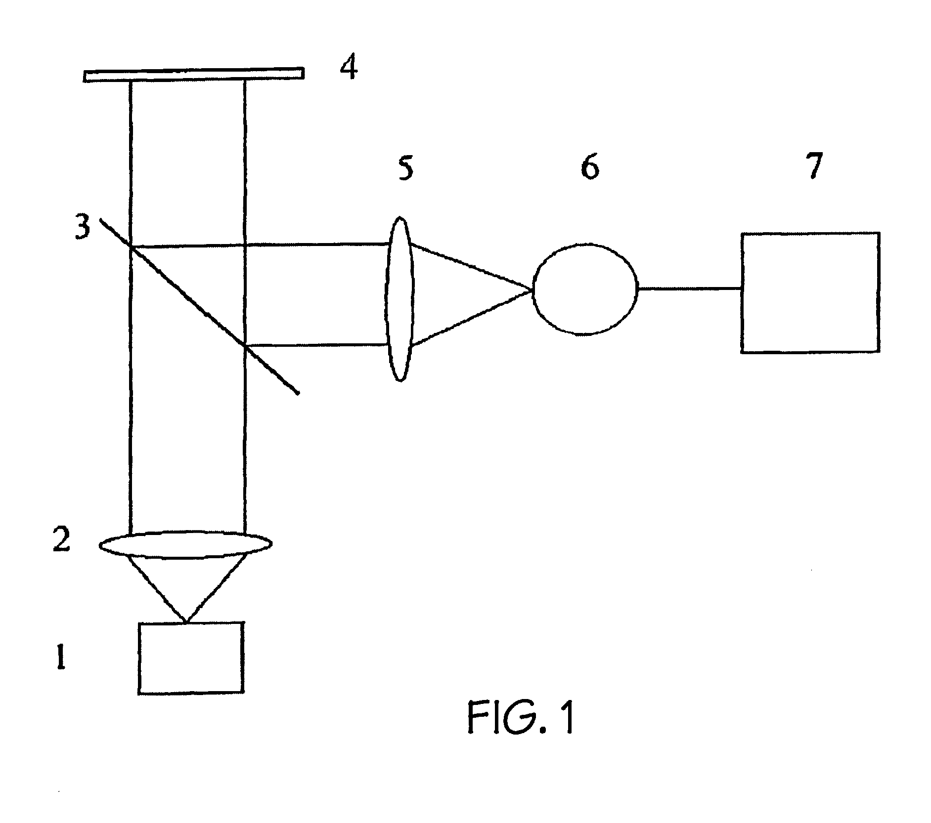
[0279] First variant of the proposed apparatus is schematically shown in FIG. 1. A substance (or several substances) capable to bind material (biological, chemical or other) components due to a biological, chemical or physical interaction is located on a surface of or inside a sensor layer 4. The substance contacts a medium (not shown in FIG. 1) that contains or presumably contains the said components. Biospecific binding (e.g. antigen-antibody, biotin-avidin), formation of chemical associations, adsorption or absorption, etc. can be named among examples of such interactions. For operation of the apparatus it is imperative not the type of interaction, but the fact that any such binding goes with superinduction of a new substance to the surface of or into the sensor layer and causes an increase (a decrease in variants according to claims 57 and 68, when the sensor layer is formed by the medium under test) of optical thickness of the sensor layer, which is registered by the apparatus....


PUM

PropertyMeasurementUnit
thicknessaaaaaaaaaa
thicknessaaaaaaaaaa
thicknessaaaaaaaaaa

Abstract

Application: detection of binding of biological and / or chemical components of liquid or gaseous mixtures and solutions, which are of mainly biological origin and / or determine parameters of living activity of biological objects, to substances that bind the said components due to a biological, chemical or physical interaction; and analysis of mixtures and solutions to determine presence of biological and / or chemical components. Essence: binding substances are arranged on a surface of or inside a sensor layer, which changes its thickness due to the binding being detected; the layer is affected by light of different wavelengths; a signal due to interference on the sensor layer is registered in the reflected or transmitted light. In the first variant, the signal is represented by a spectrum; the sensor layer is more than 10 mum thick and exceeds the maximal recorded wavelength by at least an order of magnitude; information about the binding being detected is obtained from analysis of a spectral shift of interference maximums and minimums. In the second variant, the light passes also a scanned Fabry-Perot interferometer; the recorded signal is a dependence of intensity of the resulting light upon changes of base of the scanned Fabry-Perot interferometer, in which maximums due to correlation of the spectral characteristics of interaction of the light with the sensor layer and interferometer are observed; information about the binding being detected is obtained from a shift of the said dependence along values of base. In the third variant, other interferometers are used, which are scanned due to a change of the path difference of interfering beams. The required technical result is to make measurement results independent from uncontrollable variations of intensity of the analyzed light in whole as well as in any part of its spectrum, any areas of the sensor layer, and, consequently, to increase accuracy of measurements and reliability of results, sensitivity and resolution with simultaneous reduction of the number of necessary operations, of labor input and cost of both single- and multi-channel variants including real-time registration.

Description

[0001] The proposed invention refers to the field of development of methods and tools for biological and chemical analyses.[0002] An analogue of the proposed method [U.S. Pat. No. 4,558,012, Int. Cl. G01N 33 / 54, U.S. Cl. 436 / 501, 1985] is known that is intended for detection of chemical material components and measuring their concentration by detection of their binding to a sensor layer, which comprises:[0003] irradiating of the sensor layer by light of various wavelengths, for which the sensor layer is transparent, at least, partially;[0004] registration in the reflected light of a signal, which depends upon optical thickness of the said sensor layer and is due to the fact that interference on the said sensor layer modulates the reflection spectrum of the said sensor layer;[0005] judging about the binding being detected from a change of the said signal.[0006] In this method, the sensor layer is formed on a non-metallic substrate with high optical absorption, made preferably of a se...

Claims


Application Information

Patent Timeline
Patent Type & Authority Applications(United States)
IPC IPC(8): G01N21/45G01N21/77G01N33/543G01N33/53
CPCG01N21/45G01N21/7703Y10S436/805Y10S435/808Y10S436/807G01N33/54373
Inventor NIKITIN, PETR IVANOVICHGORSHKOV, BORIS GEORGIEVICH
Owner PETR IVANOVICH NIKITIN
Why Eureka
Try Eureka