

Ebg designs for mitigating radio frequency interference
a technology of radio frequency interference and ebg, which is applied in the field of radio frequency interference prevention, can solve the problem of reducing the size of these devices
- Summary
- Abstract
- Description
- Claims
- Application Information
AI Technical Summary
Benefits of technology
Problems solved by technology
Method used
Image

Examples
example 1
[0039]An apparatus for electromagnetic interference shielding is described herein. The apparatus includes an electromagnetic bandgap (EBG) structure. The EBG structure is attached to a surface of the apparatus such that the EBG structure is to mitigate electromagnetic interference propagation within the apparatus.
[0040]The apparatus may be a chassis of an electronic device, and the EBG structure may be attached to one surface of the chassis. The apparatus may be a heat sink, and the EBG structure may be attached to one surface of the heat sink, or the apparatus may be a heat pipe, and the EBG structure may be attached to one surface of the heat pipe. Additionally, the apparatus may be a heat spreader, and the EBG structure may be attached to one surface of the heat spreader. The EBG structure may be adjusted to block a frequency band electromagnetic interference, such that a selective frequency of electromagnetic interference may be mitigated. The EBG structure may be a mushroom typ...
example 2
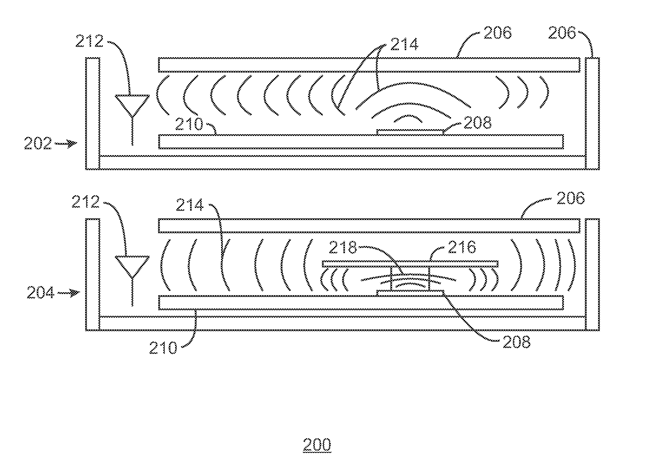
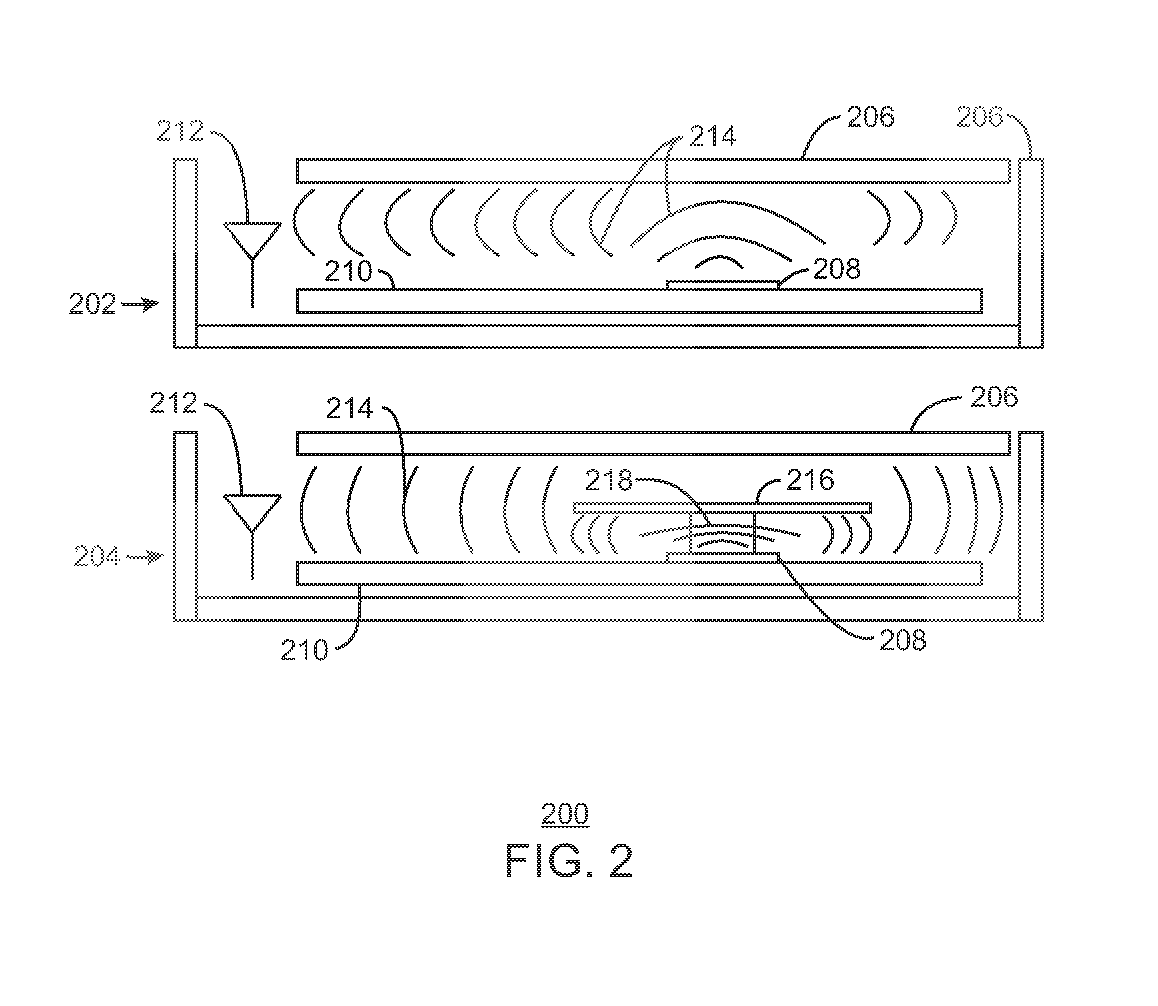
[0041]A method for constructing an electronic device with electromagnetic interference shielding is described herein. The method includes forming an enclosure of the electronic device, where the enclosure includes an electromagnetic bandgap (EBG) structure. The method also includes locating an antenna and a plurality of noise producing components within the enclosure to block noise from the plurality of noise producing components from the antenna.
[0042]The EBG structure may be a mushroom type EBG structure, or the EBG structure may be integrated with the enclosure. An arrangement of the EBG structure on the enclosure may be generated during an industrial design of the enclosure. The noise producing components include at least a central processing unit (CPU), platform controller hub (PCH), memory device, panel timing controller, motherboard layout, or any combination thereof. The EBG structure may be selected to mitigate a frequency band of the electromagnetic interference to block a...
example 3
[0043]A method for fitting an electronic device for electromagnetic interference shielding is described herein. The method includes attaching an electromagnetic bandgap (EBG) adhesive tape to a surface within the electronic device to prevent noise from interfering with the operation of an antenna.
[0044]The surface may be a housing of the electronic device. The EBG adhesive tape may include a conductive adhesive layer. The EBG adhesive tape may include a mushroom type EBG structure. The surface may be a portion of a housing of the electronic device. Further, the surface may be a heat sink, and the EBG adhesive tape may be attached to one surface of the heat sink, or the surface may be a heat pipe, and the EBG adhesive tape may be attached to one surface of the heat pipe. The surface may also be a heat spreader, and the EBG adhesive tape may be attached to one surface of the heat spreader. The EBG adhesive tape may include an EBG structure that is selected to mitigate a portion of the...
PUM
| Property | Measurement | Unit |
|---|---|---|
| electromagnetic bandgap | aaaaa | aaaaa |
| frequency | aaaaa | aaaaa |
| electromagnetic | aaaaa | aaaaa |
Abstract
Description
Claims
Application Information