Signal-level based control of power grid load systems

Active Publication Date: 2015-10-22
SIGNIFY HLDG BV
View PDF6 Cites 15 Cited by
  • Summary
  • Abstract
  • Description
  • Claims
  • Application Information

AI Technical Summary

Benefits of technology

[0008]It is an object of the present invention to provide an improved power converter system capable of supplying an electrical

Problems solved by technology

However, all of these DC devices require conversion of the building's AC power into DC for use, and that conversion typically uses inefficient rectifiers.
These AC-DC conversions (o

Method used


Image

  • Signal-level based control of power grid load systems
  • Signal-level based control of power grid load systems
  • Signal-level based control of power grid load systems

Examples


first embodiment

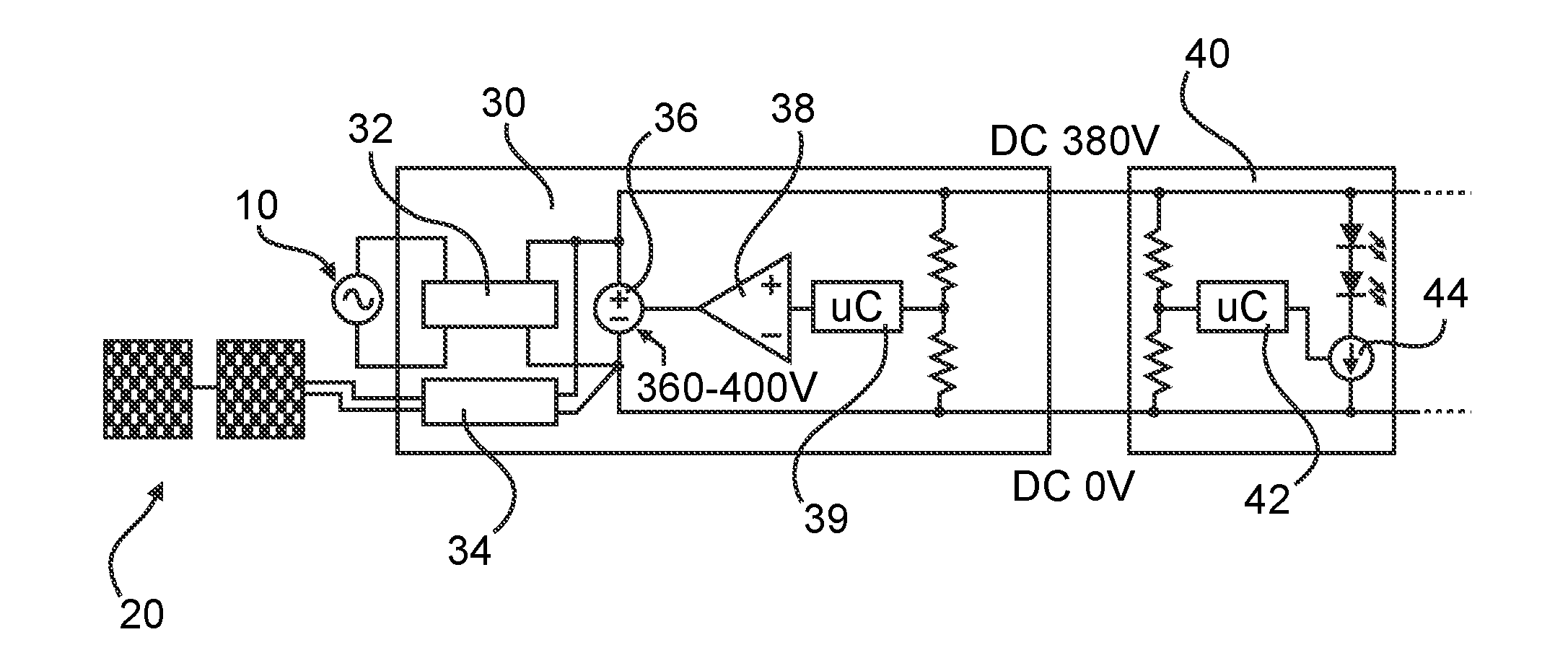
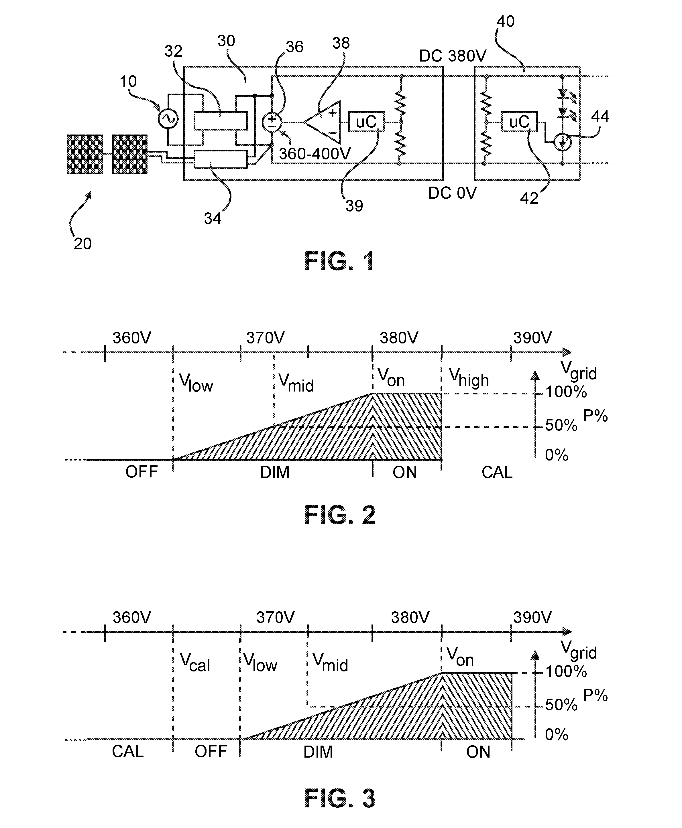
[0038]FIG. 2 shows a diagram indicating operating states for various DC grid voltages Vgrid, according to a In this example, a nominal bus voltage of e.g. 380VDC is assumed. The nominal bus voltage can be used in the embodiments to indicate 100% relative output power level P% and can thus be used as reference voltage (Von) which is below the maximum allowed voltage (Vhigh) which can be set to 386VDC in the present example, while the minimum allowed bus voltage can be set to 360VDC. Then, a voltage level of 365 VDC can be used to indicate 0% power or off-level (Vlow). All values between the 100% level and the 0% level may then linearily correspond to the requested dimming value (e.g., 372.5VDC corresponds to 50% dimming (i.e. Vmid). Of course, other non-linear relations may be possible as well, if desired.

[0039]The DC grid controller 30 can now perform on / off control and dimming for an entire group of connected DC luminaire(s) 40 or other loads or devices by suitably changing the DC...

second embodiment

[0045]FIG. 3 shows a diagram indicating operating states for various DC grid voltages, where the voltage level for signaling the optional calibration mode (CAL) is set below the off-voltage threshold (i.e. the minimum allowed bus voltage) rather than above the on-voltage threshold (i.e. minimum allowed bus voltage). Thus, the second predetermined range is located below the minimum allowed bus voltage and any voltage level below the off-voltage threshold will set the DC luminaire 40 into the calibration mode (CAL).

[0046]The control mechanisms according to the above first and second embodiments, as described so far, do not take into account the effect of a voltage drop over the cables of the DC grid. The control range 0% to 100% of the dim level is based on small voltage level variations (e.g. 365V to 380V), which is critical on grids with long cables or large loads. Not correcting for voltage drop could result in unequal dimming levels, or even luminaires turning off when they shoul...

third embodiment

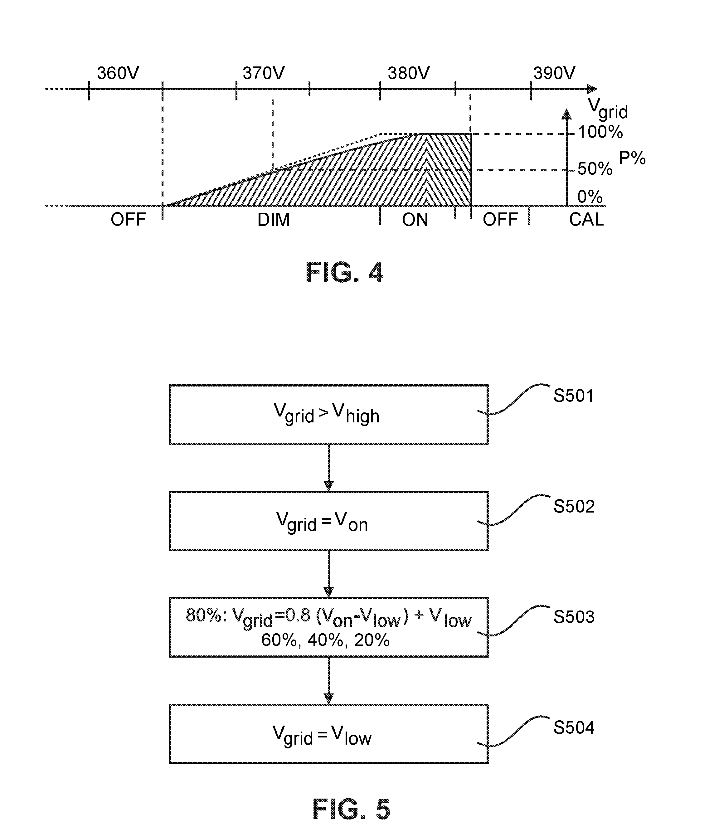
[0047]This detrimental effect is in this context even more complicated because it has a non-linear behavior. As already mentioned above, an LED driver behaves basically as a ‘constant power sink’. Regardless of the input voltage, it will try to consume the same amount of power. A reduced input voltage thus causes an increase in current, which in turn again causes more cable losses and less input voltage until an equilibrium is reached. In a system with multiple consumers (e.g. loads, luminaires or other power consuming devices of the DC grid) it is difficult or impossible to accurately determine what the input voltage for a given device will be at certain load conditions (without performing a measurement). A proposed calibration mechanism according to the following third embodiment can overcome this problem.

[0048]FIG. 4 shows a diagram indicating operating states for various DC grid voltages including a calibration state according to the third embodiment. In FIG. 4, both error curve...


PUM


Abstract

The present invention relates to a load control system in which a power cable of a DC or AC is used for on/off control and dimming of connected load devices without adding significant hardware structure. The control is achieved through a change in the DC or AC bus voltage. A grid controller can perform on/off control and dimming for an entire group of connected load devices by changing the bus voltage. Connected load devices that do understand or want to make use of this feature will be unaffected. In order to reduce the effects of voltage drop, a calibration procedure is provided. The calibration procedure first triggers the connected load devices into a calibration mode and then initiates a number of predefined output level commands that allow the load devices to build an individual correction for the undesired voltage drop.

Description

FIELD OF THE INVENTION[0001]The invention relates to the field of apparatuses and methods for controlling loads connected to a power grid. More specifically, the invention relates to on / off control and dimming of luminaires in a direct current (DC) grid lighting system.BACKGROUND OF THE INVENTION[0002]Conventional electric power systems were designed to move central station alternating current (AC) power, via high-voltage transmission lines and lower voltage distribution lines, to households and businesses that used the power in incandescent lights, AC motors, and other AC equipment. Today's electronic devices (such as computers, florescent lights, variable speed drives, and many other household and business appliances and equipment) need direct current (DC) input. However, all of these DC devices require conversion of the building's AC power into DC for use, and that conversion typically uses inefficient rectifiers. Moreover, DC power generated by distributed renewable power source...

Claims


Application Information

Patent Timeline
IPC IPC(8): H02J1/00
CPCH02J1/00H05B47/185H05B47/10
Inventor YSEBOODT, LENNARTWENDT, MATTHIASBOEKE, ULRICH
Owner SIGNIFY HLDG BV
Why Eureka
Try Eureka