Method of spectrum detection and design of detection frame structure in communication system

Inactive Publication Date: 2015-10-22
ALCATEL LUCENT SAS
View PDF6 Cites 6 Cited by
  • Summary
  • Abstract
  • Description
  • Claims
  • Application Information

AI Technical Summary

Benefits of technology

[0006]In view of the above, it is necessary to provide a detection frame structure with a shorter measurement gap for spectrum detection so as to alleviate the influence on data transmission of the current frame.
[0007]The main idea

Problems solved by technology

However it is neither necessary nor appropriate to apply the 6 ms meas

Method used


Image

  • Method of spectrum detection and design of detection frame structure in communication system
  • Method of spectrum detection and design of detection frame structure in communication system
  • Method of spectrum detection and design of detection frame structure in communication system

Examples


Example

[0031]Identical or similar reference numerals denote identical or similar components throughout the drawings.

DETAILED DESCRIPTION OF EMBODIMENTS

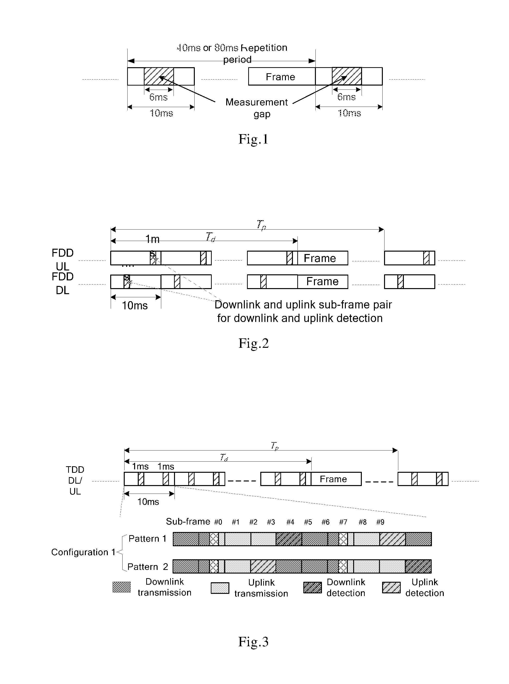
[0032]The key point of the detection frame structure of the invention is to select an appropriate detection sub-frame without influencing HARQ timing as well as broadcast and synchronization channels of the LTE-A system.

[0033]For an FDD system, the downlink sub-frame #0 and #5 can not be used for downlink detection as they carry important system information and synchronization signals. Except for these two downlink sub-frames, any other downlink sub-frame in the downlink frame can be used for downlink detection, and correspondingly an uplink sub-frame, in the uplink frame, spaced from the downlink sub-frame by 4 ms can be used for uplink detection. For example, when the downlink sub-frame #1 in the downlink frame is used for downlink detection, then the uplink sub-frame #5 in the uplink frame is used for uplink detection. The fixed 4 ms dela...


PUM


Abstract

The invention provides a method of spectrum detection in a user equipment of a communication system, the method including: for each detection period, detecting a signal from a target system in a specific downlink detection sub-frame of each frame in a detection duration; and sending a detection result to a base station at the end of the detection duration. The specific downlink detection sub-frame is a sub-frame #4 or #9 in a downlink/uplink sub-frame configuration 1; a sub-frame #4 or #9 in a configuration 2; a sub-frame #7 in a configuration 3; a sub-frame #4 or #7 in a configuration 4; and a sub-frame #3, #4, #7 or #9 in a configuration 5 of a TDD system. The specific downlink detection sub-frame is any other downlink sub-frame than sub-frames #0 and #5 in an FDD system. There is further provided a method of spectrum detection in a base station of a communication system, the method including: receiving detection result(s) from one or more user equipments; and determining whether one or more frequency bands of a target system are available according to the detection result(s).

Description

FIELD OF THE INVENTION[0001]The present disclosure relates to a communication system and particularly to the spectrum detection and the design of detection frame structure in a communication system.BACKGROUND OF THE INVENTION[0002]The 3rd generation partnership project (3GPP) Long Term Evolution (LTE) system has been considered as one of the most promising cellular networks in the future. In LTE-Advanced (LTE-A), technologies such as carrier aggregation, advanced MIMO, relay, etc., are further incorporated to enhance the performance of the system. Despite these valuable features, the scarce of spectrum resources still hinders the LTE-A system from realizing its full potential.[0003]While on the other hand, there are underutilized spectrum resources remaining on those frequency bands with low or even no activities. For example, Ultra High Frequency (UHF) band TV white spaces (TVWSs), which have been released due to the transition of analog TV to digital TV, can be opportunistically a...

Claims


Application Information

Patent Timeline
IPC IPC(8): H04W16/14H04W72/04H04J3/12
CPCH04W16/14H04W72/0453H04J3/12H04W72/00H04L1/1861H04L1/1893H04L5/143H04L5/1469H04L27/0006H04W36/0085
Inventor XU, BINYANGZHANG, JUNHE, GAONING
Owner ALCATEL LUCENT SAS
Why Eureka
Try Eureka